


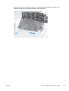
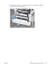
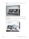
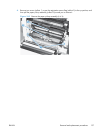

3. Release one tab (callout 1), remove the stopper (callout 2), and then disconnect one connector
(callout 3).
Figure 2-55 Remove the laser/scanner assembly (2 of 4)
1
2
3
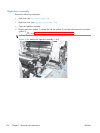
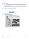
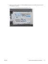
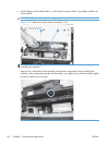
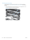
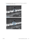
4. Release one tab (callout 1), and then slide the cable guide (callout 2) in the direction that the
arrow indicates.
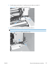
5. Remove the cable guide (callout 2) and the flat cables (callout 3) together, and then remove one
spring (callout 4).
Figure 2-56 Remove the laser/scanner assembly (3 of 4)
4
3
2
1
ENWW
Removal and replacement procedures
133