


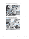
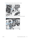
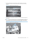

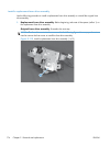

4. From the top of the product, look at each shutter arm. Make sure that they are in the closed
position (callout 1). If they are in the open position (callout 2), carefully push on the shutters to
close them.
Figure 2-105 Install the main drive assembly (4 of 8)
2
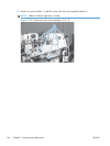
1
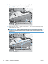
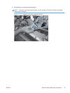
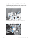
5. Make sure that the six sheet-metal screw tabs (callout 1) on the drive assembly are flat against the
product chassis.
NOTE: If the tabs are not flat against the chassis, the developer-disengagement drive gears and
cams—on the back side of the drive assembly—are not properly aligned with, and seated in, the
corresponding holes on the product. Remove the drive assembly, realign it, and then reinstall it.
See
Figure 2-103 Install the main drive assembly (2 of 8) on page 168.
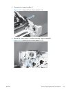
Figure 2-106 Install the main drive assembly (5 of 8)
1
ENWW
Removal and replacement procedures
169