


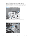
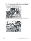
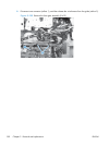
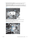
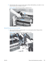
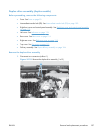
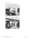

2. Replacement fuser drive assembly: Fasten the replacement fuser gear assembly to the
product with four screws. Install the screws in the order shown below (callouts 1 to 4).
Original fuser drive assembly: Install, but do not fully tighten four screws (callouts 1 to 4).
Carefully push the drive assembly to the left (toward the right-door side of the product) until it
slightly shifts forward. Apply steady pressure to hold the assembly in place, and then tighten the
screws.
Figure 2-126 Install a replacement fuser gear assembly (2 of 3)
1
2
3
4
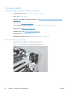
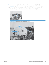
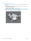
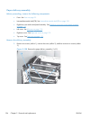
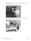
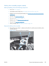
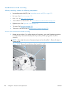
3. Replacement fuser drive assembly: Release two tabs in the order shown below
(callouts 1 and 2). and then remove the spacer (callout 3).
Original fuser drive assembly: Installation complete—this step is not required.
Figure 2-127 Install a replacement fuser gear assembly (3 of 3)
1
2
3
ENWW
Removal and replacement procedures
183