


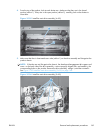


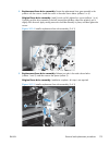
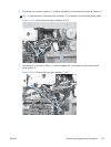
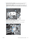

2. Remove one screw (callout 1), release four tabs (callout 2), and then separate the first transfer
high-voltage power supply (callout 3) from the product.
CAUTION: The PCA is still connected to the product.
Reinstallation tip When you reinstall the power supply PCA, look through the holes on the
PCA (callout 5) and make sure that the contact springs are correctly positioned against the back
side of the PCA.
Figure 2-117 Remove the fuser gear assembly (2 of 9)
1
2
3
4
5
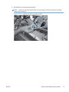
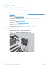
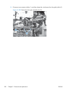
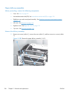
3. Disconnect one connector (callout 1) and then remove the first transfer high-voltage power supply
(callout 2).
Figure 2-118 Remove the fuser gear assembly (3 of 9)
1
2
ENWW
Removal and replacement procedures
177