


Model 5328A
Maintenance
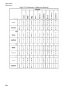
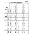
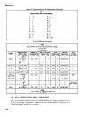
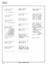
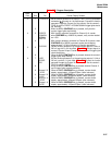
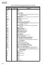
Table 5-8A. Program Description
Check
Point
Test
Observe on 5328A
1
REMOTE
Front panel (RMT) annunciator should be on.
2
CHECK
Counter should read 10.000 MHz.
3
RESOLUTION
The 9825A should print and counter display the 10 MHz
check signal with resolutions from 0.1 Hz to 1.0 MHz.
4
FREQ A
Counter display should read 0.0000 KHz.
5
RATlO B/A
Counter display should read 0.0000000
6
PERIOD A
Counter display should read 0. s
7
PER. AVE. A
Counter display should read 0.00000 ns
8
T.I. A-B
Counter display should read 0. s
9
T.I. AVG. A-B
Counter display should read 0.00000 ns
10
FREQ C
Counter display should read 0.0000 KHz
11
RATIO C/A
Counter display should read 0.0000000
12
SAMPLE RATE
When calculator displays MANUAL OK?, verify that front
SINGLE/
panel SAMPLE RATE control can be manually adjusted as
MULTIPLE
seen from GATE LIGHT flashing rate.
MEASMNT
When calculator displays GATE LIGHT OFF?, verify that Gate
Light is truly off.
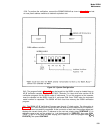
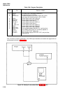
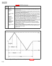
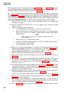
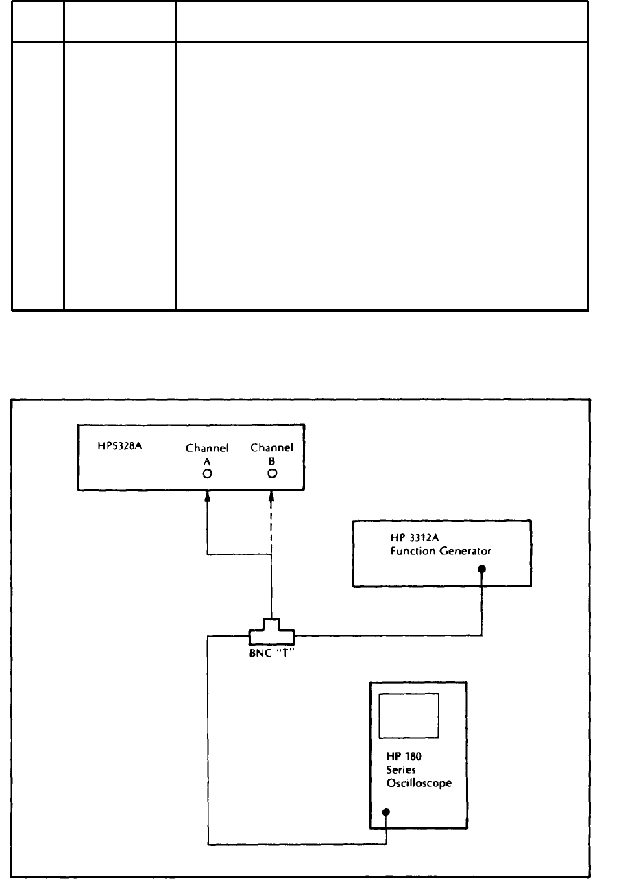
5-42. Connect a function generator to the 5328 input channels and monitor the signal with an
oscilloscope as shown in Figure 5-8.
Figure 5-8. Hookup for tests described in Table 5-8B & C
5-36