


Model 5328A
Operation
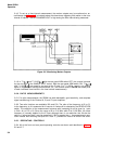
3-49. Channel C Input
3-50. The CHANNEL C 500 MHz
500
input is useful for higher frequency signals out of the
A and B input channel range (0 to 100 MHz).
CAUTION
The “C” channel input signal should be limited to 5 volts maximum.
If this limit is exceeded the inline fuse may open (blow).
3-51. “C” Channel Overload lndicator
3-52. The OVERLOAD (CHANNEL C) indicator will flash on and off if the voltage maximum
is exceeded at the “C” channel input.
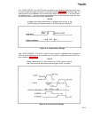
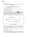
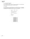
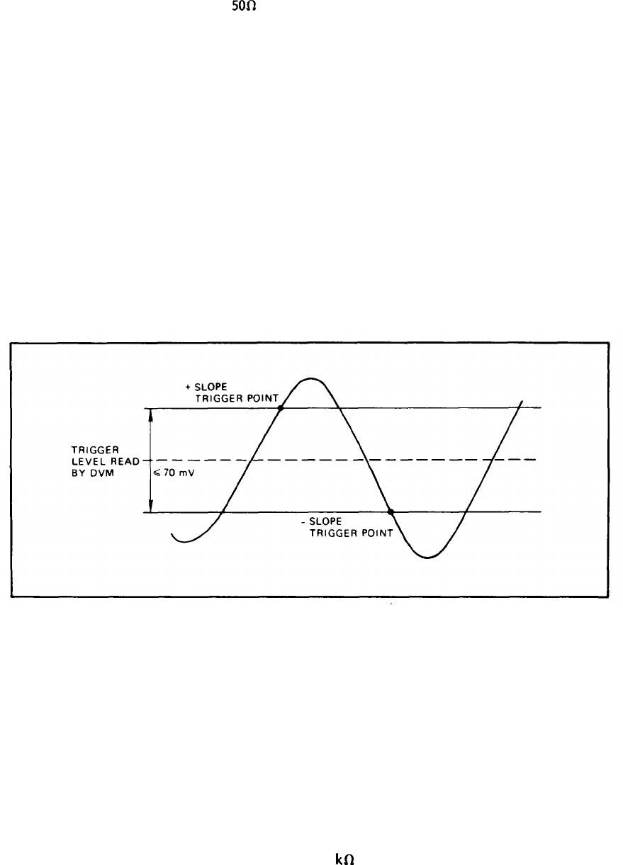
3-53. Hysteresis Band of Trigger Levels
3-54. The width of the trigger level hysteresis band, shown in Figure 3-77 is determined by the
sensitivity of the counter. For frequencies below 40 MHz, it is typically less than 25 mV peak-to-
peak. At frequencies from 40 MHz to 100 MHz, it is typically less than 70 MHz peak-to-peak. The
signal must pass through the entire hysteresis band before a trigger pulse is generated. If the
SLOPE switch is set to “+”, the trigger pulse occurs at the top of the hysteresis band. If the SLOPE
switch is set to “-”, the trigger pulse “occurs at the bottom” of the hysteresis band.
Figure 3–11 Hysteresis Band
3-55. Since trigger level measurements indicate the center of the hysteresis band, a better
value for the actual trigger level may be obtained by subtracting one-half the hysteresis band
(“-” slope) or adding one-half the hysteresis band (“+” slope). A typical value for the width of
the hysteresis band is 30 mv peak-to-peak.
3-56 The value to use for the hysteresis band depends on the frequency; or, for pulses, it de-
pends on the rise time.
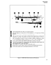
3-57. External Frequency Standard Input
3-58. The rear panel external frequency standard (EXT OSC IN) input is useful for locking
the counter to a high stability external frequency standard. This external standard must be 1,
2.5,5, or 10 MHz, with an amplitude of >1V rms into 1
kfl
(maximum input of 5 volts peak-to-peak).
3-12