


Model 5328A
Maintenance
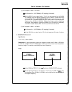
5-11. Inspection
5-12. The 5328A should be inspected for indications of mechanical and electrical defects. Elec-
tronic components that show signs of overheating, leakage, frayed insulation, and other signs
of deterioration should be checked and a thorough investigation of the associated circuitry
should be made to verify proper operation. Mechanical parts should be inspected for excessive
wear, looseness, misalignment, corrosion, and other signs of deterioration.
5-13. Cleaning
5-14. The instrument should be kept free of dust, moisture, grease, and foreign matter to
ensure trouble-free operation. A dry clean cloth, a soft bristled brush, or a cloth saturated with
cleaning compound may be used.
WARNING
100/120/220/240 VAC SUPPLY WIRES ARE EXPOSED WHEN
EITHER TOP OR BOTTOM COVER IS REMOVED. USE EXTREME
CAUTION DURING TROUBLESHOOTING, ADJUSTMENT, OR
REPAIR. AVOID DAMAGE TO INSTRUMENT BY REMOVING
POWER BEFORE REMOVING OR REPLACING COVERS, ASSEM-
BLIES, OR COMPONENTS.
5-15. Performance Test
5-16. GENERAL. The performance test (Table 5-4) and test card sheets that follow the test can
be used to verify and record proper operation of all circuits of the counter and may also be used:
a.
As part of an incoming inspection check of instrument specifications.
b. Periodically, for instruments used in systems where maximum reliability is important.
c.
As part of a procedure to locate defective circuits.
d. After any repairs or adjustments and before returning instrument to regular service.
e.
As a permanent record of instrument maintenance performed, because the test record
pages may be removed.
5-17. REPAIR
5-18. Printed Circuit Component Replacement
5-19. Component lead holes in the circuit boards have plated-through walls to ensure good
electrical contact between conductors on opposite sides of the board. To prevent damage to the
plating and the replacement component, apply heat sparingly, and work carefully.
5-20. Replacing Integrated Circuits
5-21. Following are two recommended methods of replacing integrated circuits:
a.
SOLDER GOBBLER. This is the best method. Solder is removed from board by a solder-
ing iron with a hollow tip connected to a vacuum source,
b. CLIP-OUT. This method should be used as a last resort only. Clip the leads as close to
the base as possible. With a soldering iron and long nose pliers, carefully remove the
wires from each hole. Then clean the holes.
5-3