


Model 5328A
Theory of Operation
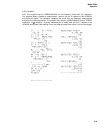
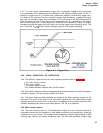
4-18. Ratio
4-19. By replacing the time base with a second input of frequency, f
2
; the same configuration
as in Figure 4-2 can be used to measure the ratio f
2
/f. For higher resolution the signal at fre-
quency f can be divided in decade steps in a manner identical to multiple period averaging.
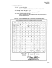
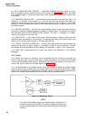
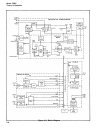
4-20. Time Interval
4-21. Figure 4-3 shows the configuration for the measurement of time between two events or
time interval. The main gate is now opened by the START input and closed by the STOP. The
decade divider output is again counted and the display shows the elapsed time between START
and STOP signals. The measurement of time interval is considered in more detail in para-
graph 4-22.
4-22. TIME INTERVAL, RESOLUTION, AND AVERAGING TECHNIQUES
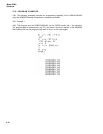
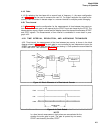
4-23. Time interval, the measurement of the time between two events, is shown in the block
diagram shown in Figure 4-3. The main gate is now controlled by two independent inputs, the
START input opening the gate and the STOP input closing it. Clock pulses are accumulated for
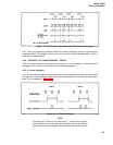
START and STOP. This is shown in Figure 4-4.
Figure 4-3. Basic Elements of a Time Interval Counter
Figure 4-4. Clock Pulses
NOTE
In a time interval measurement, clock pulses are accumulated for the
duration the main gate is open, The gate is opened by one event,
START and closed by the other, STOP.
4-3