


Model 5328A
Operation
SECTION Ill
OPERATION
(OPERATORS INSTRUCTIONS)
3-1. INTRODUCTION
3-2. This section contains information necessary to understand how to control and use the
counter. Specific details and examples are provided for making measurements of frequency,
period, period average, time interval and time interval average, and ratio. How to use the ex-
ternal frequency standard input is described. Programming information for use with the HP-IB
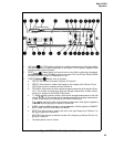
Interface and the Programmable Input Module is provided. Front and rear panel controls, con-
nectors, and indicators are described.
3-3. FREQUENCY MEASUREMENTS
3-4. To make a frequency measurement on a CW signal below 100 MHz, select FREQ A func-
tion, select the appropriate input signal conditioning, and apply the signal to A input. The
RESOLUTION switch determines the resolution of the measurement. Since the 5328A is a con-
ventional counter, 1 Hz resolution is obtained in 1-second of measurement time (e.g., .1Hz
10 seconds). The .1 Hz best case frequency resolution limits the low frequency measurement
accuracy. In practice, low frequencies are measured by making a period or period average
measurement and inverting the result to obtain frequency.
3-5. To make a frequency measurement on a CW signal in the range of 30 to 500 MHz, select
FREQ C function and apply the signal to the Channel C input. Make sure that the amplitude
does not exceed 5V rms. The trigger level for the Channel C is fixed at 0V dc. If pulse wave-
forms are being measured, they must cross through 0 volts dc by at least 25 mV. Pulse widths
down to 1 ns can be counted.
CAUTION
DO NOT exceed 5 volts rms at “C” channel input. Circuits in this
channel may be damaged by higher voltages.
3-6. The A, B, and C input modules are direct count modules. Direct count allows greater reso-
lution per-second of measurement time than prescaling techniques and is important in making
frequency measurements on pulse bursts since the allowable measurement time is fixed (it
must be less than the width of the burst).
3-7. When the 5328A is in FREQ A or FREQ C function and the rear panel ARM switch is OFF,
a measurement cycle is initiated (i.e., arms the counter) upon the first trigger level crossing at
the A (or C) input. This means that pulsed signals are measured as easily as CW if the measure-
ment time (determined by the RESOLUTION switch) is less than the width of the pulse.
3-8. With the ARM switch ON, FREQ A and FREQ C are armed by a trigger event at the B in-
put. This mode is useful whenever it is desired to have real time control over when a measure-
ment is to begin. Useful applications include measuring frequency variations along a frequency
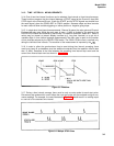
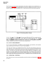
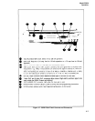
burst and linearity testing of sweep generators. Figure 3-7 illustrates the setup for measuring
the linearity of a sweep generator. The Channel B Trigger level is adjusted to trigger (and there-
by arm the counter) at various points along the sweep out waveform. By plotting the B trigger
levels and the corresponding frequency measurements made at those levels, the linearity of the
generator may be determined.
3-1