


Model 5328A
Operation
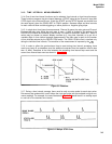
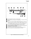
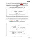
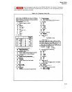
3-47. SLOPE SWITCH. The ±SLOPE switch (provided for each channel) determines which slope
of the input signal will trigger the counter. As a simple example, (Figure 3-9) if the pulse width of a
positive pulse is to be measured, the A channel slope switch would be set to “+” and the B chan-
nel would be set to “-” (for time interval measurements the A channel always begins the mea-
surement and the B channel ends the measurement).
NOTE
A simple pulse width measurement is achieved with the use of the
+SLOPE setting for Channel A and the -SLOPE setting for Channel B.
Figure 3–9. Slope Switch Settings
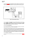
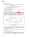
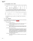
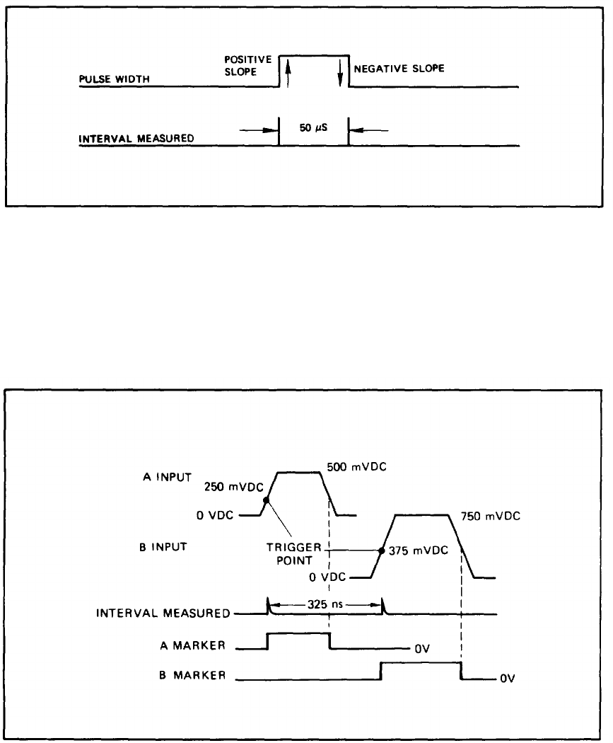
3-48. LEVEL CONTROL. The LEVEL control for each channel is adjustable over the range of
±2.5V dc with the attenuator for that channel in the X1 position. A typical use of the LEVEL con-
trols is shown in Figure 3-10.
NOTE
Simple measurement of a time interval, the LEVEL control of the A
and B input channels were used to set the trigger LEVEL of A and B.
Figure 3-10. Level Control Settings
3-11