


Model 5328A
Operation
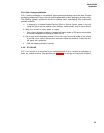
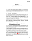
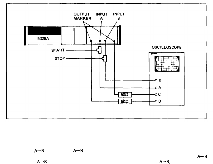
3–18. To set up a time interval measurement, the marker outputs may be monitored on an
oscilloscope (see Figure 3-5) to indicate where the channels are triggering with relation to the time
interval of interest. The GATE/MARKER OUT is high during the time interval being measured.
Figure 3-5. Monitoring Marker Outputs
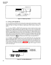
3–19. In T.I.
A-B
and T.I. AVG
A-B
with the rear panel ARM switch OFF, the counter is armed
by the run down of the SAMPLE RATE control. With the rear panel ARM switch ON, T.I.
A-B
and T.I. AVG
A-B
are armed by an event at the C input. For T.I. AVG
A-B,
only one arming
signal is required per average measurement (i.e., the counter doesn’t need to be armed prior
to each individual time interval in the time interval measurement).
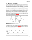
3-20. RATIO MEASUREMENTS
3-21. For ratio measurements, the 5328A has wide bandwidth, good sensitivity, and complete
signal conditioning of the Channel A, B, and C input amplifiers.
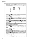
3–22. Two ratio functions are available: B/A and C/A. The ratio of the frequency at B (or C)
to the frequency at A is measured for N counts of A where N is selected by the RESOLUTION
switch. The resolution of the measurement improves with increasing N and is given by 1 part
in B/A x N (or C/A x N). Since the range of A is 0-10 MHz while B is 0-100 MHz, the lower
frequency is normally applied to the A input although there is no restriction that this be the
case (i.e., ratios less than 1 may be measured). If B/A is greater than 1, the measurement reso-
lution is better than switching the inputs for a ratio <1, provided the value of N remains the same.
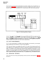
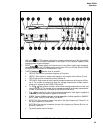
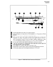
3-23. OPERATING CONTROLS
3–24. All of the front and rear panel operating controls are shown and described in Figures
3-6 and 3-7.
3-4