


Model 5328A
Theory of Operation
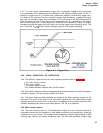
4-112. When the interface receives a data byte, for control of trigger levels, it goes into the
DAC control mode. This is a result of the interface receiving a + or - on its input data lines. Once
in the DAC control mode, the programming interface latches disregard the information at their
input. Simultaneously, the information, on the input data lines (MDA-MDD) is accepted by the
A11 DAC board.
4–113. The A11 DAC board shifts the polarity indicator and three following numerical bytes
of information into its shift registers. Following the polarity indicator and the three numerical
data bytes, an asterisk (*) appears on the MDA-MDD lines (see Table 4-7 for proper format).
The asterisk causes the programming interface to revert back to the non-DAC control mode.
In this mode, the All board stops accepting data, and the programming interface latches again
accept the input data.
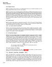
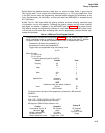
Table 4-1. 5328A Input Circuit Program Code Set
Programming is accomplished as detailed in Section Ill with the additions below. Codes
shown underlined are start up conditions. These conditions are set by the code “P”, Remote
Programm Initialize, or by the bus commands Device Clear, or Selected Device Clear.
Commands to A channel are preceded by A
Commands to B channel are preceded by B
Trigger levels are programmed using the following format
±X.Y Z*
Where X is volts
Y is 100 s of mV
Z is 10 x of mV
* is used to terminate inputs to the DAC’s
Control
Function
Coupling
AC
DC
Slope
+
Atten
X1oo
X1o
x1
Separate/Corn
Separate
Common A
NOTE
Underlined codes are default conditions.
Invert
Normal
B8
A&B Inverted
B9
The check function overrides all other programming commands for A&B channels.
EXAMPLES:
The instruction:
CMD “?U9”, “PF:G5S137A3579-1.25*B37+1.65*R”
Input circuits related programming information
Will program a 5328A with listen address of 9 to:
Function
Channel A
Channel B
Time Interval Avg A to B
DC Coupled
DC Coupled
Multiplier
103
-Slope X1 Atten
Multiple measurement X1 Atten
Trig Level +1.65V
Continuous Cycle
Common A
+Slope
Manual sample rate control
Trigger Level -1.25V
Code
2
3
4
5
1
6
7
A8
A9
4-15