


Model 5328A
Operation
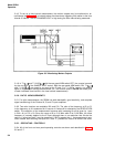
3-13. TIME INTERVAL MEASUREMENTS
3-14. One of two time interval functions can be selected, time interval or time interval average.
These functions measure the time interval between a START signal at the Channel A input and
STOP signal at the Channel B input. If both the START and the STOP signals are derived from
the same signal, place the COM A-SEP in COM A position. Separate slope and level controls
for each channel allow variable triggering on either positive or negative going slope.
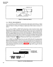
3–15. In single-shot time interval measurements, Channel A opens the main gate and Channel
B closes the main gate. While the main gate is open, 10 MHz is divided by the setting of the
RESOLUTION switch and totalized by the counter. For optimum resolution, select N=1. Other N
values may be chosen to prevent display overflow (e.g., long time intervals) or to get rid of
unstable digits. In time interval average measurements, the main gate is open for the number
of time intervals selected by the RESOLUTION switch. The 5328A 10 MHz clock is totalized only
during the individual time intervals. The resolution of the measurement is improved by the
fi.
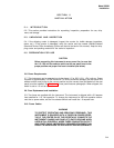
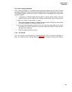
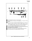
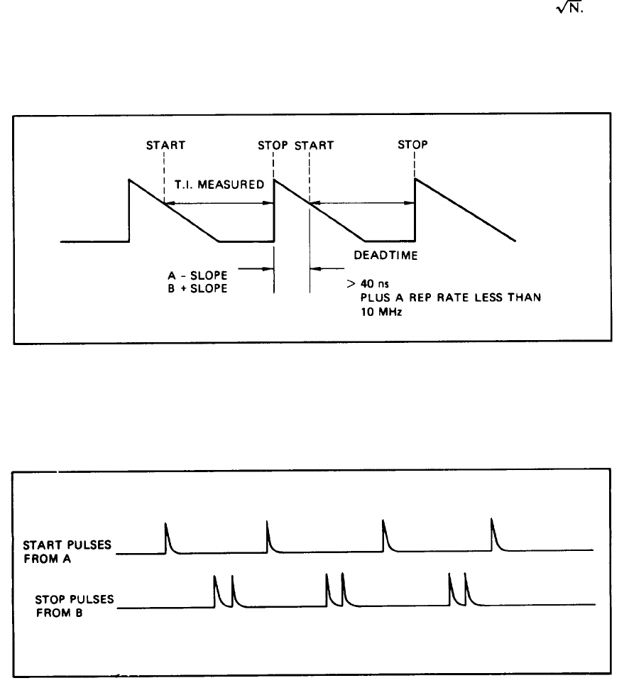
3-16. In order to allow the synchronizers time to reset during time interval averaging, there
must be at least 40 ns deadtime (and the additional constraint that the repetition rate be less
than 10 MHz). Deadtime is the time between the preceding time interval stop event and the
current time interval start event as shown in Figure 3-3.
Figure 3-3. Deadtime
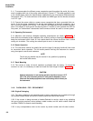
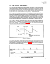
3-17. During a time interval average, there must be only one stop pulse for each start pulse.
Extraneous stop pulses which occur before the next start pulse are accumulated and give erro-
neous readings. For example, the case illustrated in Figure 3-4 would result in a reading equal
to one-half of the desired time interval.
Figure 3-4. Multiple STOP Pukes
3-3