


Model 5328A
Theory of Operation
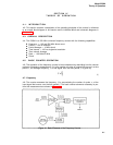
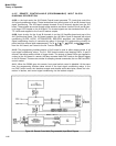
counting decades, output multiplexing logic, and synchronizers to generate precise timing
signals for the main gate. The oscillator section contains the input/output logic to accept an
external signal via the rear panel or an internal signal from the oven-regulated crystal oscillator.
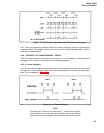
4-54. The sample rate circuit controls the instrument display cycle.
Inhibit, reset, main gate,
transfer, and sample rate signals are generated in this circuit, as is the BCD digit address code
for the strobed display. Generation of decimal point and annunciators and decoding of BCD
data are accomplished by the display control circuits. Data out of the decade counting assembly
or the input modules is decoded and displayed on the nine-digit LED display.
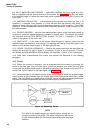
4-55. The A4 Function Selector serves as the main signal switch of the instrument. It routes
input signals through multiplexer to the decade counting assembly and/or the time base. At
the same time, it interacts with the display control circuits to determine the beginning and end
of the display cycle. The precision main gate signal is created on the function selector through
interaction with the time base assembly. The function selector also has extensive interaction
with the input modules. It is the main receiver of the high-speed data from the modules and
the originator and receiver of module arming pulses.
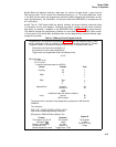
4–56. The flexibility of the 5328A comes from the ability of all these operating subsections to
accept diverse data from input modules. This is accomplished through the use of a 4000-bit
read-only memory (ROM) as the master control of the instrument. Located in the main counter
section of the instrument, the ROM accepts the four-bit function code and the three-bit time
base code from the front-panel switches or the HP-IB remote programming board. The ROM
generates 32 bits of output data which are transmitted throughout the instrument to set-up each
subsection for the particular measurement situation.
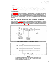
4-57. Input Section
4-58. The input modules are the main interface between the instrument and the outside elec-
tronic environment. They accept input signals and convert them into the proper form to be
handled by the main counter circuits.
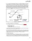
4-59. The middle area of the input module section provides the 5328A with extended fre-
quency capability (Channel C). A
50fl fuse-protected 500 MHz amplifier and Schmitt trigger
feed the 500 MHz decade. Latches in this section strobe the ninth (least-significant) digit from
the module onto the data bus and into the display. In functions not requiring an input from this
module, ROM lines deactivate the output strobing circuitry and the ninth digit on the display
goes blank.
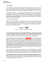
4-60. Hewlett-Packard Interface Bus (HP-US) Section
4-61. The fourth section of the instrument, the HP-IB assembly provides for control of the
counter by the HP-IB. Connected to the main instrument bus through a ribbon cable, the
internally-mounted HP-IB board controls function, time base, cycle rate, arming, and other
controls in the instrument.
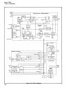
4-62. A1 MOTHERBOARD
4-63. The A1 Motherboard consists of five sections, as follows:
a.
Display control.
b. State control.
c. Oscillator.
d. Decade Counting Assembly.
e.
Time Base.
4-9