


Model 5328A
Theory of Operation
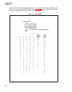
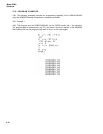
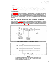
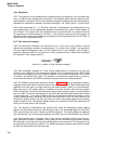
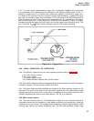
4-9. INPUT AMPLIFIER AND TRIGGER — essentially conditions the input signal to a form
that is compatible with the internal circuitry of the counter. As Figure 4-7 indicates, the output
of the amplifier/trigger is a pulse train where each pulse corresponds to one cycle or event of the
input signal.
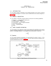
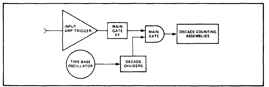
4-10. TIME BASE OSCILLATOR —
is that element of the counter from which the time, t, of
equation (1) is derived. From equation (1) it may be seen that the accuracy with which t is
determined has a significant effect on the measurement accuracy of the frequency, f. The 5328A
employs a 10 MHz temperature-controlled (oven-regulated) precision, crystal oscillator as the
time base element.
4-11. DECADE DIVIDERS —
take the time base oscillator signal as the input and provide as
an output a pulse train whose frequency is variable in decade steps. The operator can control
this frequency with the FREQ RESOLUTION, N switch. The time, t, of equation (1) is deter-
mined by the period of this pulse train.
4-12. MAIN GATE —
is the heart of the counter. When this gate is opened, pulses from the
amplifier/trigger are allowed to pass through. The opening and closing of the main gate is con-
trolled by the decade divider output to the main gate flip-flop.
4-13. DECADE COUNTING ASSEMBLIES —
totalizes the output pulses from the main gate and
displays this total after the gate is closed. If, for example, the gate is open for precisely 1 second,
the decade counting assemblies (DCA’s) display the frequency, in Hertz, of the input signal.
4-14. Other basic measurements the counter can perform are described in the following
paragraphs.
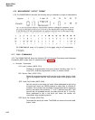
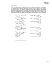
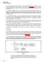
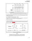
4-15. Period
4-16. Period, the inverse of frequency, can be measured with the counter by reversing the
inputs to the main gate. Now the input signal controls the duration over which the main gate
is open and the decade divider output is counted by the DCA’s. The duration of the count is, of
course, one cycle or period of the input signal (see Figure 4-2).
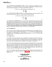
4-17. Unused decades in the decade divider chain can be used to divide the amplifier/trigger
output so that the gate remains open for decade steps of the input period rather than a single
period. The is the basis for multiple period averaging. Period and period averaging techniques
are used to increase measurement accuracy on low frequency measurements.
Figure 4-2. Measuring Period
NOTE
The roles of the amplifer/trigger and decade divider outputs are re-
versed in measuring the period. This same configuration also serves
for ratio measurements with the second input replacing the time base
oscillator.
4-2