


Model 5328A
Maintenance
Table 5-4. Performance Test [Continued)
.
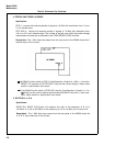
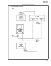
Set channels A and B of the 5328A to DC coupling, COM A, X1 ATTEN, and FREQ A.
.
Set the 6516 Test Oscillator for an output of 100 Hz at 6 volts peak-to-peak. Center
the signal on the oscilloscope B channel display.
l
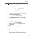
Execute the following from the 9825A keyboard:
wrt 701, “PF4G6S13A379+000*B37+000*R”
l
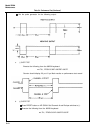
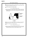
Adjust the display of the A channel marker output (on channel A of the oscillo-
scope) such that the top of marker waveform just barely intersects the positive slope
and negative slope of the 100 Hz sine wave. Verify that this occurs at 0 volts on the
100 Hz sine wave.
l
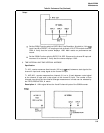
Connect the counter’s B Marker Output to the A channel of the oscilloscope.
Verify that the top of the marker intersects the 100 Hz sinewave at 0 volts.
.
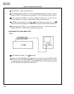
Execute the following from the 9825A keyboard:
wrt 701,
“PF4G6S13A379+200*B37+200*R”
c
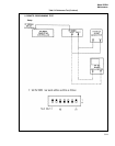
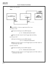
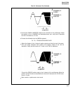
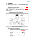
Adjust the display of the B channel marker output such that the top of the marker
just barely intersects both positive and negative slopes of the 100 Hz waveform.
Verify that this occurs at +2 volts on the 100 Hz waveform as shown.
5-16