


Model 5328A
Maintenance
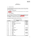
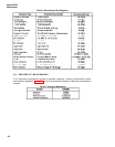
Table 5-4. Performance Test (Continued)
b.
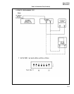
10 MHz to 100 MHz
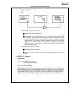
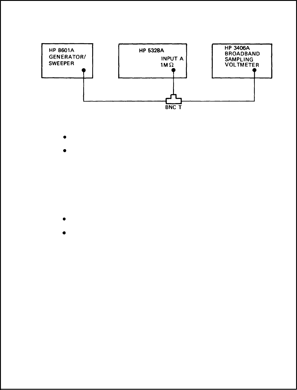
Setup:
2.
(1) DC coupled 10 MHz to 100 MHz
.
Set the 5328A to DC COUPLING.
.
Set the “8601A for an output level of 15 mV rms as measured on the 3436A
RF voltmeter. Vary the 6601A’s frequency from 10 MHz to 35 MHz and verify
that the counter displays correct frequency readings. Increase the 8601A
output level to 50 mV rms and vary the frequency from 35 MHz to 100 MHz.
Verify that the counter displays correct frequency readings. Adjust 5328A
LEVEL A control as necessary to obtain stable display. Mark results on
performance test record.
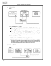
(2) AC coupled 10 MHz to 100 MHz
.
Set the 5328A to AC coupling.
l
Set the 8601A for an output level of 15 mV rms and repeat part 2 of step (1.)
above.
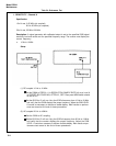
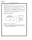
SENSITIVITY - Channel B
Specification:
15 mV rms,0-35MHz (dc coupled)
20 Hz-35 MHz (ac coupled)
50 mV rms, 35 MHz-100MHz
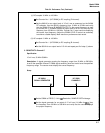
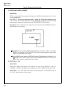
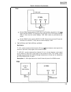
Description: A generator with calibrated output drives the B channel of the 5328A under
test. The frequency of the B channel MARKER OUTPUT is measured by a second frequency
counter. The generator is set to the specified 5328A signal sensitivity level and varied over
the specified frequency range. The second counter must display the correct frequency.
Adjustments of the 5328A LEVEL B control may be necessary to achieve a stable count.
5-5