


Model 5328A
Theory of Operation
SECTION IV
THEORY OF OPERATION
4-1. INTRODUCTION
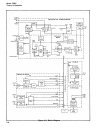
4-2. This section contains a description of the operating principles of the counter in reference
to an overall block diagram in this section and to individual block and schematic diagrams in
Section Vlll.
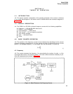
4-3. OVERALL DESCRIPTION
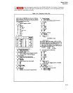
4-4. The 5328A is a 500 MHz universal frequency counter with the following capabilities.
4-5.
Frequency —
100 and 500 MHz direct count
Period —
100 ns resolution
Period Average — 10 MHz clock
Time Interval — 100 ns single-shot resolution
Time Interval Average
Ratio —
100 MHz/10 MHz
Check
BASIC COUNTER OPERATION
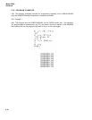
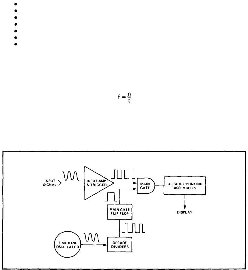
4-6. The operation of the frequency counter is best understood by describing how the counter
performs a frequency measurement. If n is the number of cycles of a signal that occurs in a time
period, t, the average frequency, f, of that signal over the time period, t, is given by
(1)
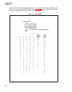
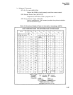
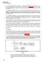
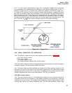
4-7. Frequency
4-8. The counter measures the frequency, f, by accumulating the number of cycles, n, of the
input signal that occurs over the time period, t. The basic counter elements necessary to per-
form this measurement are shown in Figure 4-1.
Figure 4-1. Basic Elements of the Frequency Counter
4-1