


Model 5328A
Maintenance
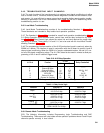
5-43. TROUBLESHOOTING INPUT CHANNELS
5-44. The main function of the input channels is to perform input signal conditioning via either
local or remote control, Therefore, effective problem diagnosis is divided into two sections, local
and remote. It is most efficient to assure proper local operation before remote section trouble-
shooting is performed. Use of the Performance Test (Table 5-4) will aid in determining which
troubleshooting section to use.
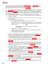
5-45. Local Mode Troubleshooting
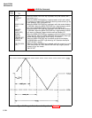
5-46. Local Mode Troubleshooting consists of the troubleshooting flowchart in Figure 5-5.
These flowcharts are intended to help isolate local operation problems.
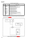
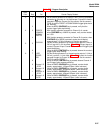
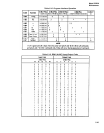
5-47. The flowchart in Figure 5-5 is intended for overall local operation troubleshooting. Table
5-10 Relay Operation shows required levels, control lines, and the relay involved for any func-
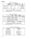
tion. Table 5-11 Relay Control Logic shows the output line and level required for proper relay
operation in a function. These tables, 5-10 and 5-11, are to be used with the Local Mode Trouble-
shooting Flowchart (Figure 5-5).
5-48. The programming interface section of the A10 Synchronizer board is used only when the
5328A is in remote. The interface is used in conjunction with the All board to control A and B
channel signal conditioning. When the 5328A is in remote, addressable latches, U8 and U15, con-
trol all of the signal conditioning relays. The A11 DAC board is also used in remote to allow pro-
gramming of the A and B channel trigger levels.
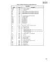
Table 5-10. A12 Relay Operation
J-1 Pin #
Function
J-1 PIN
Relay Controlled
HI
LO
2
Channel A Slope
—
+
———
5
Channel B Slope
—
+
———
6
Channel B Atten
X1
X10
K6, K11, K10
7
Channel B Coupling
DC
AC
K9
10
SEP/COM
COM
SEP
K4, K5
12
Channel A Atten
X1
X10
K2, K3, K8
14
Channel A Coupling
DC
AC
K7
NOTE: Nongrounded pins on J-1 should float to TTL high.
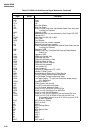
Table 5–11. Relay Control Logic
Function
Channel A
Channel B
Slope
+
A10J3 Pin 2 Low
A10J3 Pin 5 Low
A10 J3 Pin 2 High A10J3 Pin 5 High
X1
A10J3 Pin 12 High
A10J3 Pin 6 High
Attn X10
A10J3 Pin 12 Low
A10J3 Pin 6 Low
X100
A10J3 Pin 13 High
A10J3 Pin 8 High
Coupling
A10J3 Pin 14 Low
A10J3 Pin 7 Low
A10J3 Pin 14 High
A10J3 Pin 7 High
SEP, COM A
SEP A10J3 Pin 10 Low
COM A A10J3 Pin 10 High
5-49. Remote Mode Troubleshooting
5-50. The following information includes Programming Logic Troubleshooting and DAC
Troubleshooting. These areas will help isolate remote operation problems where A and B input
channels operate correctly in local control.
5-41