


Model 5328A
Theory of Operation
operation of the state control circuit U4 on the motherboard. Diode CR3 ensures that LINH is
low to inhibit the counter during the time that LRST is low.
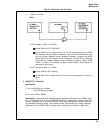
4-197. STROBE ENABLE DECODER. Decoder U13 is a 4- to lo-line decoder used to strobe the
various storage latches. Pins 1, 14, and 15 are used to select the device to be strobed and pin 2
is an enable which determines the width of the strobe pulse. The output of U25C disables U13
when the ASM is in the decision state mode. In the decision state mode, the format bit U22(17)
goes high which disables U13.
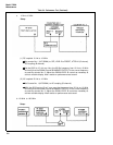
4-198. REMOTE PROGRAM STORAGE. Storage circuits U28, U33, and U34 are used to program
instrument functions. U28 stores Time Base codes in 3-bit bytes and U34 stores Function codes
in 4-bit bytes. U33 stores 8 bits of information, one-bit at a time. The Sample Rate, Arming,
Storage Off, and Decade Reset can be programmed by U33. In addition, U33(4,5, and 6) control
the manner in which measurements are made and output to the bus. The inputs to the remote
program storage circuits are the Module Data A, B, C, and D lines from DIO lines, 1,2,3, and 4,
respectively.
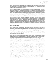
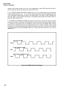
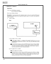
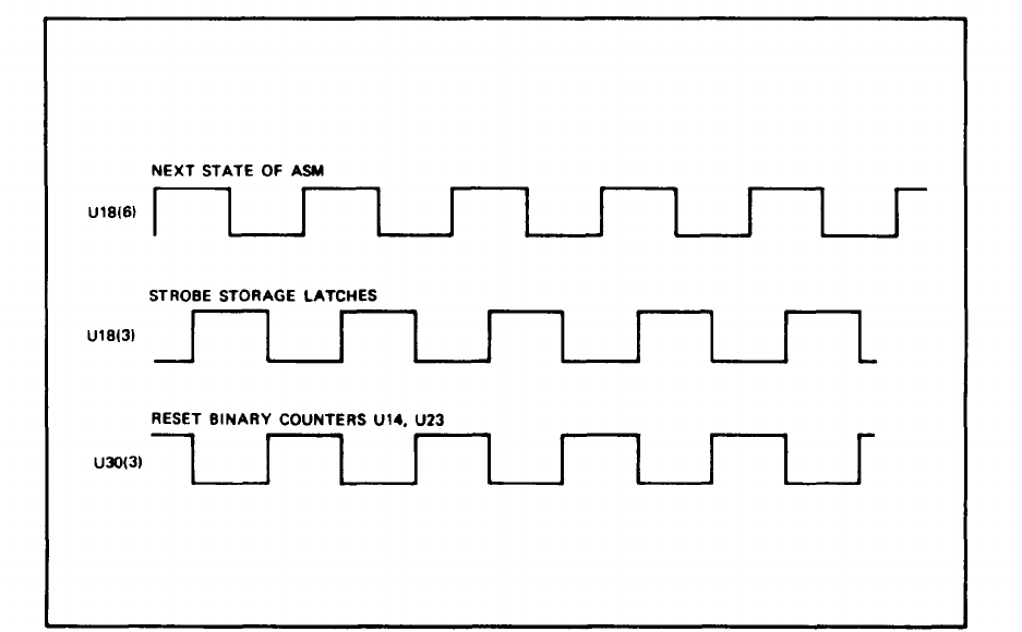
Figure 4-10. ASM Oscillator Timing Diagram
4-24