


Model 5320A
Operation
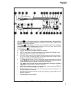
3-59. Marker Outputs
3-60. Two marker output connectors are mounted on the front panel. These outputs represent
the Channel A and Channel B Schmitt triggers. The outputs provide 0 to 300 mV levels into
50Q
delayed by less than 20 ns. These outputs are useful for oscilloscope monitoring, Time
interval measurement setups are simplified if the time interval of interest and the marker out-
puts can be simultaneously displayed on oscilloscope traces. Frequency measurements on noisy
signals can be made with more confidence since the markers can indicate the presence of noise
triggering. These outputs are protected from inadvertently applied voltage to ±5V dc.
3-61. Gate/Maker Out
3-62. the GATE/MARKER OUT rear panel connector supplies a TTL level which is high when
the counter’s main gate is open and low when it is closed. Monitoring the GATE OUT on an
oscilloscope can provide this information for applications where the markers do not give the
desired information.
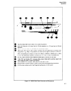
3-63. 1 MHz and 10 MHz Frequency Standard Outputs
3-64. The 1 MHz OUT and 10 MHz OUT connectors are on the rear panel. When terminated
in 50 ohms, the output is a square wave of approximately l-volt amplitude.
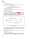
3-65. Trigger Lights
3-66. A trigger light is provided for each (A and B) input channel to enable the user to know
not only if the channel is triggering, but also in which direction the trigger level must be ad-
justed to cause triggering. The light is ON when input is above the trigger level; OFF when in-
put is below the trigger level; BLINKING when channel is triggering. The trigger lights are
operative over the full frequency range of dc to 100 MHz.
3-67. The trigger lights can be used with a 10:1 oscilloscope probe to provide a logic probe
function. By adjusting the trigger level to one-tenth (since using 10:1 divider probes) of the
threshold voltage for the logic family under investigation (e.g., .14 volts for TTL), the light in-
dicates the logic state of circuit points which are contacted with the probe. When the trigger
level light is ON, the circuit node is a high (i.e., above the threshold voltage). If the light is OFF,
the node is a logical low. If the light blinks, then pulses (up to 100 MHz rep rate) are present at
the node. The trigger lights can also detect the polarity of low rep rate pulses down to 5 ns pulse
width. Positive pulses cause the light to blink on while negative pulses cause the light to blink
off.
3-68. PROGRAMMING OPERATION
3-69. The 5328AF/096/H42 Universal Counter is fully compatible with the Hewlett-Packard
Interface Bus (HP-1B) IEEE Standard 488-1975 Appendix C.
3–70. Procedures for verification of proper operation of the 5328AF/096/H42 in the remote
mode are contained in paragraphs 5–37 through 5-42.
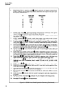
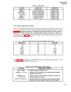
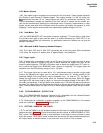
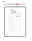
3-71. SETTING ADDRESS SWITCHES
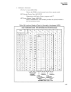
3-72 To use the 5328A in an HP-IB based system the first step is to set the rear panel address
switches shown in Table 3-4. The left-most switch sets the counter to ADDRESSABLE or TALK
ONLY mode. ADDRESSABLE mode is used whenever a calculator or other controller is used
within the system. TALK ONLY mode is used when the counter will be controlled manually but
will output results to another device on the bus such as a printer or D/A converter.
3-13