


Model 5328A
Theory of Operation
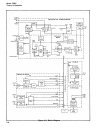
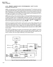
4-107. REMOTE CONTROLLABLE
DIAGRAM DESCRIPTION
(PROGRAMMABLE) INPUT BLOCK
4-108.
I n the local mode, the A19 Switch Control board generates TTL levels that control the
A12 signal conditioning relays. These levels allow front panel control of A and B channel input
signal conditioning. The A19 board accepts inverted A and B channel signals from the A12
board. These signals are routed through pulse stretcher and driver circuits to the A and B chan-
nnel trigger LEDs located on the A19 board. The inverted signals are also translated from ECL to
TTL levels and supplied to the A and B marker outputs.
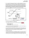
4-109. Input circuitry for the A and B channels is on the A12 Amplifier board and part of the
A10 Synchronizer board. The A12 board contains the 100 MHz A and B channels with signal
conditioning SLOPE, AC/DC, ATTENUATORS, SEP/COM, amplifiers, and Schmitt triggers.
Signal conditioning circuitry is controlled by relays K1 through K12 synchronizing circuitry for
period and time interval type measurements. The A,
~,
B, ~, TI
,~,
GOSC, and
GOSC
outputs,
from the A10 board, are routed to the A4 Function Selector.
4-110. The programming interface section of A10 board is used to allow remote control of all
input signal conditioning relays. The A11 DAC board contains two identical DACs, A and B
channel, that allow remote control of trigger levels. The outputs of these DACs are supplied to
a relay on the A12 board. In remote, the relay connects these DAC levels to the Schmitt trigger
on the A12 board. There are two modes of accepting remote commands, the non-DAC and DAC
control modes.
4-111. When the 5328A goes into remote, front panel switch control is disabled. At the same
time, the programming interface takes control of the input signal conditioning relays. In the
non-DAC control mode, the interface accepts and decode serial data bytes, stores the infor-
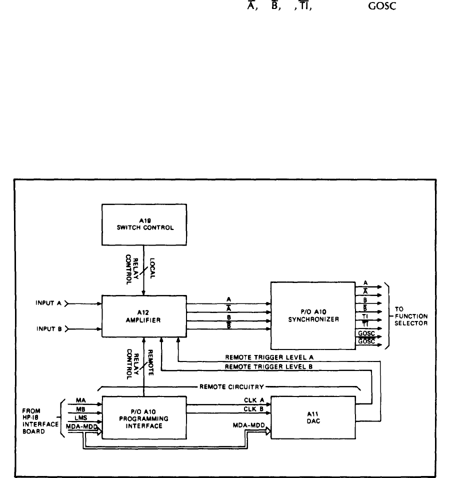
mation in latches, and control signal conditioning via the latched outputs.
Figure 4-9. Remote Controllable (Programmable) Input Block Diagram
4-14