


Model 5328A
Operation
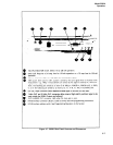
3-25. FUNCTION OF CONTROLS, INDICATORS, INPUTS, AND OUTPUTS
3-26. The following paragraphs provide a detailed description of the function of controls, indi-
cators, and connectors.
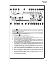
3-27. Display
3-28. The 5328A counter display consists of nine-digit, seven-segment LED display and annun-
ciators for indicating the measurement units of Hz, s, as well as multiplier indicators (K, m,
~,
n). These display units and multipliers are automatically displayed along with the correct deci-
mal point location. Overflow (OVFL) indicates that left-most-significant digits have overflowed
the display. Remote (RMT) indicates that the counter (HP-IB interface) is under remote program
control. A GATE lamp indicates that the counter has been armed and that a measurement is
in process.
3-29. Power (Line)
3-30. The LINE switch puts the counter in OPER (operate) or STBY (standby). The STBY
position with STBY light on turns off some but not all the power supply voltages. This circuit
arrangement allows the high stability oscillator to operate continuously. Therfore, the input
to main power transformer (T1) plus the unregulated dc voltage to the oscillator oven is always
energized whenever power is connected even with the line switch in STBY.
3-31. Reset
3–32. The RESET pushbutton resets the display and internal count to zero and also initiates
single measurements when the SAMPLE RATE control is in the HOLD mode, The HP-IB interface,
provides remote control capability, pushing the RESET button restores the counter to local con-
trol (when not remotely locked out by the HP-IB Local Lockout universal command). Refer to
programming in this section.
3-33. Sample Rate Control
3–34. The SAMPLE RATE control sets the minimum time between samples, The time is con-
tinuously variable from less than 2 milliseconds between measurements to HOLD, which holds
the display indefinitely.
NOTE
The counter will internally (self) arm (via the SAMPLE RATE control)
only when ARMing is OFF and the FUNCTION selected is at other
than FREQ A, FREQ C, and RATlO C/A.
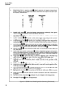
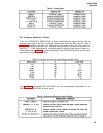
3-35. Arming
3-36. The counter may be armed internally (i.e., made ready to start a measurement) by the
SAMPLE RATE control, or externally by the input signal itself, (arming off) or by a signal not
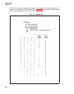
directly involved in the measurement (arming on). Table 3-7 is an arming status table. A rear
panel switch turns ARMing either ON or OFF. The counter is armed within 1
ps
after the event
at the B arming input and is armed within 10
ps
after the event of the C arming input.
3-8