


Model 5328A
Theory of Operation
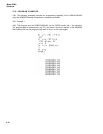
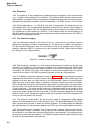
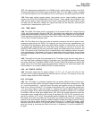
4-38. FREQUENCY MEASUREMENT ERROR. The error caused by the ambiguity is in ab-
solute terms, ±1 of the accumulated count. For a frequency measurement the signal counted is
the input signal of frequency, f
in
. Thus the relative error is given by:
±1 count error, relative frequency measurement error
(2)
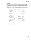
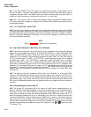
4-39. PERIOD MEASUREMENT ERROR. For period measurement, the signal counted is the
internal time base clock of period t
c
. Hence the relative error becomes:
±1 count error; relative period measurement error
(3)
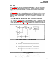
4-40. MAIN GATE REQUIREMENTS. The ±1 count error described above assumes the main
gate itself does not contribute any error. As with any gate, however, the main gate does exhibit
propagation delays and takes finite times to both switch on and off. Any differential between the
times taken for the main gate to switch on and off show up as uncertainties in the length of time
the gate is open. This uncertainty in turn translates into a measurement error that increase the
±1 count. However, the uncertainty in the main gate of the 5328A is substantially less than the
period of the highest frequency counted, so this error is not appreciable.
4-41. Time Base Error
4-42. Any error in the time base oscillator directly translates itself into a measurement error.
Thus, if the total of all the oscillator errors amount to 1 x 10
-6
, the total error contributed by the
time base in the measurement of a 10 MHz signal is 1 x 10
-6
x 10
7
= 10 Hz. Similarly, for the
measurement of a 100-millisecond period, the error would be 1 x 10
-6
x 10
-1
= 1 x 10
-7
or 100
nanoseconds.
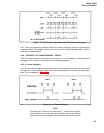
4-43. Trigger Error
4-44. Noise on the input signal will cause uncertainties in the point at whit} the Schmitt trig-
ger switches. Provided the noise is not large enough to cause false triggering (i.e., cross both
limits of the hysteresis band which would produce more pulses out of the Schmitt trigger than
input cycles to it) no significant error is introduced in a frequency measurement.
4-45. For period measurements, however, this uncertainty produces like error in the time the
gate is open, since it is this signal that controls the gate. It can be shown that with essentially low
frequency noise and a signal-to-noise ratio of 40 dB, the resultant worst case trigger error is .32%
of the period. Thus, the trigger error in the measurement of the period of a 1 kHz signal is 3.2x
10
-3
x 10
-3
= 3.2 microseconds, worst case. For 60 dB signal-to-noise ratio, worst case error
is .032%; while for a 20 dB signal-to-noise ratio signal it is 3.2%.
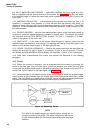
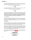
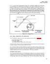
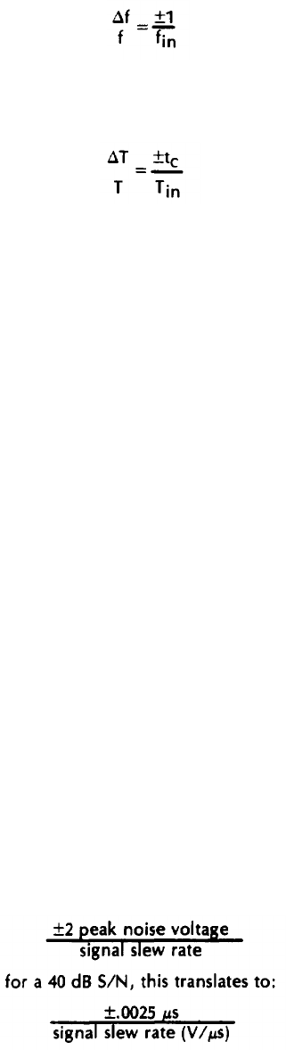
4-46. For an arbitrary wave shape (but constant slew rate through the hysteresis band), the
trigger error takes on a different expression. In Figure 4-7, it is shown that for this case, the
trigger error is:
4-6