


Model 5328A
Theory of Operation
4-178. Overall Operation
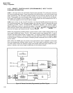
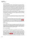
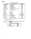
4-179. The heart of the HP-IB Interface is a 256 state algorithmic state machine (ASM) con-
trolled by a 256x16 ROM (U22) as shown in the block diagram. This state machine has two dif-
ferent format states determined by the format (F) bit from U22. One state (F=0) is an output
mode state where the machine will proceed sequentially to the next state (address) after storing
or outputting information. The other state (F=1) is a mode where the machine can either pro-
ceed to the next line or perform a conditional jump to a different line in the program. The de-
cision as to which state is chosen is made on the basis of where the qualifier bit from U11A is
low or high. Preset counters U14 and U23 provide presetting to a jump state when F=1 and the
qualifier is low. These counters increment their count in all other cases. Altogether, there are
52 different bits that may be selected as the qualifier for a particular state.
4-180. Qualifier negate circuit U30C can invert the qualifier bit for any given state so that the
machine can branch on the qualifier being low or being high. U7 is added for psuedo sub-
routine capability. In the output mode, the ASM goes through the same group of states once
for every character being outputted on the bus. U7 is incremented every time so that the ASM
can tell which character it is to output.
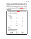
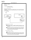
4-181. Bus Command Mode
4-182. In this mode (ATN low), the ASM accepts parallel bytes of information and decodes
them into bus commands. This usually requires setting or clearing bits of storage in U19 or U26.
4–183. Listen Mode
8-184. In the listen mode, the listen qualifier of U26 must be low and ATN high. The interface
will then accept 8-bit parallel bytes continuously. When receiving the ASCII characters P, Q,
U, R, or T the counter will act upon the byte immediately (refer to programming in Section Ill).
When receiving the letters F, G, A, B, C, D, or S the interface will then route any ASCII number
or numbers following these letters into particular storage registers. These registers are U28,
U33, and U34 along with any that are contained in any of the optional modules installed in the
mainframe.
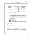
4-185. Talk Mode
4-186. The HP-IB Interface will go into the talk mode if the talk qualifier of U26 is low or the
talk always switch is set to talk always and ATN high for both cases. There will be no output in
normal operation unless a completed measurement is present and has not been outputted. The
information to be put on the bus is latched into latches U15 and U24. These drive the high cur-
rent buffers U5
)
U10, and U16, Counter U7 is used as a pointer for the ASM to recognize which
character in the serial output string the interface is to output.
4-187. A15 Circuit Operation
4-188. The following paragraphs describe the circuit operation of the HP-IB Interface.
4-189. STATE COUNTERS. The state of the ASM ROM (current state and next state) is deter-
mined by State Counters U14 and U23. These counters from an 8-bit presettable binary counter,
When pin 1 of U25 is low, the counters will always increment. When pin 1 of U25 is high, the
counters will preset (jump to another state in the program) if the output of U30C is high. The
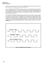
preset address is supplied to the State Counters input from the ROM. The program is shown
in the operational flowchart, Figures 5-4, 5-5, and 5-6. The output of U30C is determined by
the “not” bit from the ROM (through U21E) and the output of the Qualifier FF U11A. The pre-
programmed state of the “not” bit determines whether a high or low output of the qualifier
FF will result in a jump in the program. (This is shown in the ASM Operational Flowchart, by
4-22