


Model 5328A
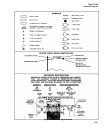
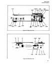
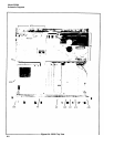
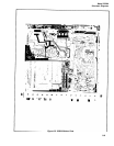
Schematic Diagrams
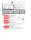
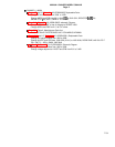
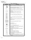
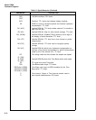
MNEMONIC
A
x
R
(AO)
R (A1)
B
B
C
C
C ARM
CLK
Data A
Data B
Data C
Data D
Digit A
Digit B
Digit C
Digit D
DVM
F Code A (FA)
F Code B (FB)
F Code C (FC)
F Code D (FD)
FS
GOSC
GOSC
HDS
HDSA
HLS
RL (HOPN)
HPL
HRD
HRS
HRTB
R (HTBA)
Table 8-1. Signal Mnemonics
DESCRIPTION
Output of Time Interval Unit, A channel. ECL levels.
Non-latched ROM bits that drive Arming Multiplexer select
lines on Function Selector. TTL levels.
Output of Time Interval Unit, B channel. ECL levels.
Output of C module, the carry input for the FS decade.
ECL levels.
Active high TTL line used for module C arming
measurement.
Clock. Digit address clock to display. TTL levels.
TTL 4-bit BCD code. Data going to display and HP-IB.
TTL 4-bit digit address code. Controls interchange
of data.
Frequency line counted by Function Selector to give display
reading. ECL level.
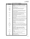
Function code from function switch. TTL levels.
Function Selector.
Gated oscillator. ECL levels.
TTL level high disables synchronizers.
Used by Option 011 HP-IB Interface to strobe bus data in
remote listener.
TTL level line used to strobe latches.
Latched ROM line which locks open Function Selector
main gate.
Same as LDP.
High resets decades. TTL active high.
High strobes 4K ROM, TTL active high.
High resets time base. TTL active high. Also resets
Function Selector.
Non-latched ROM bit which enables the TTL level Channel A
signal from the Function Selector to be counted by the
Time Base.
8-4