


Model 5328A
Schematic Diagrams
SECTION Vlll
SCHEMATIC DIAGRAMS
8-1. INTRODUCTION
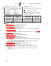
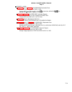
8-2. This section contains schematic diagrams and part locators. The part locators shown the
location by reference designator.
8-3. SCHEMATIC DIAGRAM SYMBOLS AND REFERENCE DESIGNATORS
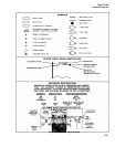
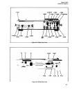
8-4. Figure 8-1 shows the symbols used on the schematic diagrams. At the bottom of Figure
8-1, the system for reference designators, assemblies, and subassemblies are shown.
8-5. Reference Designations
8-6. Assemblies such as printed-circuit boards are assigned numbers in sequence, A1, A2, etc.
As shown in Figure 8-1, subassemblies within an assembly are given a subordinate A number.
For example, rectifier subassembly A1 has the complete designator of A25A1. For individual
components, the complete designator is determined by adding the assembly number and sub-
assembly number if any. For example, CR1 on the rectifier assembly is designated A25A1CR1.
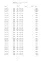
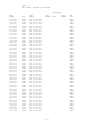
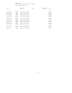
8-7. SIGNAL MNEMONICS
8-8. Table 8-1 contains a list of the mnemonics used to identify signals on the schematic
diagrams.
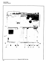
8-9. IDENTIFICATION MARKINGS ON PRINTED-CIRCUIT BOARDS
8-10. HP printed-circuit boards (see Figure 8-1) have four identification numbers: an assembly
part number, a series number, a revision letter, and a production code.
8-11. The assembly part number has 10 digits (such as 05328-60018) and is the primary identi-
fication. All assemblies with the same part number are interchangeable. When a production
change is made on an assembly that makes it incompatible with previous assemblies, a change
in part number is required. The series number (such as 1704A) is used to document minor elec-
trical changes. As changes are made, the series number is incremented. When replacement
boards are ordered, you may receive a replacement with a different series number. If there is
a difference between the series number marked on the board and the schematic in this manual,
a minor electrical difference exists. If the number on the printed-circuit board is lower than
that on the schematic, refer to Section VII for backdating information. If it is higher, refer to the
loose leaf manual change sheets for this manual. If the manual change sheets are missing, con-
tact your local Hewlett-Packard Sales and Service Office. See the listing on the back cover of
this manual.
8-12. Revision letters (A, B, etc.) denote changes in printed-circuit layout. For example, if a
capacitor type is changed (electrical value may remain the same) and requires different spac-
ing for its leads, the printed-circuit board layout is changed and the revision letter is incre-
mented to the next letter. When a revision letter changes, the series number is also usually
changed. The production code is the four-digit seven-segment number used for production
purposes.
8-1