


Model 5320A
General Information
SECTION I
GENERAL INFORMATION
1-1. SCOPE OF MANUAL
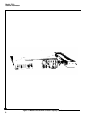
1-2. This manual provides operating and service information for the Hewlett-Packard Model
5328A/H42 500 MHz Universal Frequency Counter. (In this manual its name will be abbreviated
to “5328A” or “counter”.) A separate operators booklet contains condensed operator instructions.
1-3. This manual is divided into eight sections as listed and described below:
Section I
Section II
Section Ill
Section IV
Section V
Section VI
Section VII
Section Vlll
GENERAL INFORMATION —
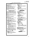
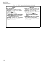
Describes the counter, lists specifications, lists
items supplied, lists items required, but not supplied, describes applications,
and lists recommended maintenance and test equipment.
INSTALLATION —
Provides instructions for unpacking, inspection, prepar-
ation for use, preparation for reshipment, and preparation for storage.
OPERATION —
Provides operator instructions including frequency, measure-
ment of input signal: time period, time period average, time interval, time
interval average, and ratio between frequencies of two input signals.
THEORY OF OPERATION —
Covers a. description of the general operating
principles of the counter with reference to block and schematic diagrams
of each assembly.
MAINTENANCE — Contains maintenance and service information, including
a list of assemblies, recommended test equipment, performance checks, and
adjustment. Troubleshooting procedures and flowcharts are included in this
section.
REPLACEABLE PARTS —
Provides a complete list of replaceable parts and
parts ordering information.
MANUAL CHANGES —
Contains information on manual changes.
CIRCUIT DIAGRAMS —
Contains schematic diagrams and component lo-
cating illustrations.
1-4. DESCRIPTION
1-5. The 5328A counter can be used to measure frequency, period, period average, time
interval, time interval average, and ratio. The 5328A provides a 9-digit LED display, display
storage, and leading zero blanking. Decimal point and unit readouts are displayed automatically.
Two independent selectable input channels are provided for time interval measurements. Each
input channel has an attenuator, trigger slope selector, level control, ac or dc coupling, and an
oscilloscope marker output. Rear panel connectors provide a gate output, one- and 10-mega-
hertz output, and an input for an external frequency standard. An ARM switch on the rear panel
allows arming by the signal being measured (switch OFF) or by another input signal (switch ON).
1-6. INSTRUMENT IDENTIFICATION
1-7. Hewlett-Packard instruments have a 2-section, 10-character serial number (0000A00000),
which is located on the rear panel. The 4-digit serial prefix identifies instrument changes. If
the serial prefix of your instrument differs from that listed on the title page of this manual, there
are differences between this manual and your instrument. Instruments having higher serial
prefixes are covered with a “Manual Changes” sheet included with this manual.
1-1