


Model 5328A
Maintenance
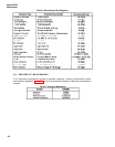
Table 5-4. Performance Test (Continued)
l
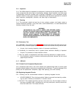
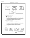
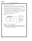
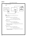
Set the 651B to 1.0 MHz and 500 mV rms.
.
Set the 5328A Function switch to T.I. A-B; Freq Resolution, N switch to 1 MHz, 1; Level A
and B to PRESET; AC coupling on both channels, X1 ATTEN on both channels, COM A.
l
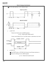
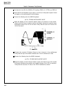
Set the Channel A SLOPE to (+) and the Channel B SLOPE to (–). Verify that the
counter displays 0.5 µs ±0.25 µs. Mark results on performance test record.
l
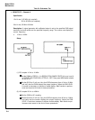
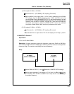
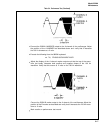
Set 5328A Function switch to T.I. AVG A+B and Freq Resolution, N switch to 1 Hz,
I(F.
Verify that the counter displays 500.XXXX ns. Mark results on performance test record.
l
Change Channel A SLOPE to (-) and Channel B SLOPE to (+). Verify that the counter
displays 500.XXXX ns. Mark results on performance test record.
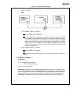
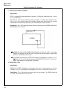
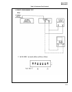
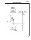
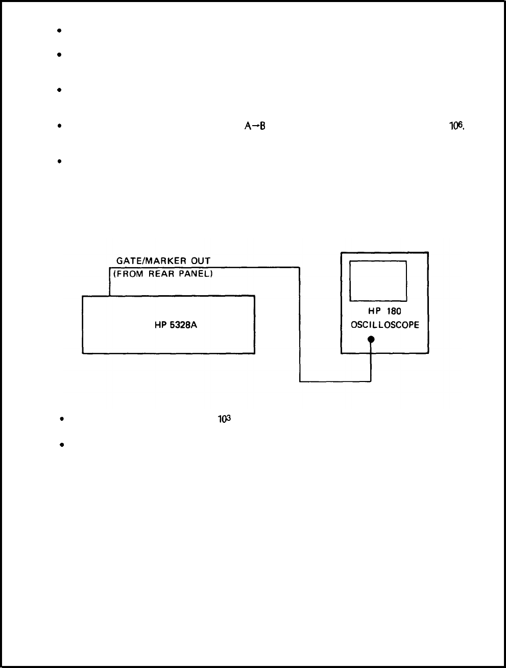
7. GATE/MARKER OUT AND SAMPLE RATE
Setup:
l
Set the 5328A to CHECK, 1 kHz,
l@
Resolution.
l
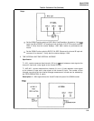
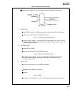
Observe the GATE/MARKER OUT signal from the counter. Vary the SAMPLE RATE
control to full ccw. The GATE/MARKER OUT signal must be greater than 2.4 Vdc and
the sample delay (time during which GATE/MARKER OUT is Low) must be less than
2 msec. Mark results on performance test record.
5-10