


Model 5328A
Theory of Operation
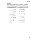
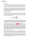
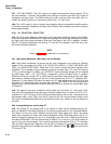
4--47. For time interval measurements, trigger error is generally negligible when compared
to the systematic error introduced by the uncertainty in the setting of trigger levels. For an un-
certainty in trigger level of ±10 millivolt and a peak noise voltage of one millivolt, trigger error
is a factor of five less than the error caused by trigger level uncertainty, regardless of signal
slew rate. For example, trigger level uncertainty of ±10 millivolt on a 100 millivoIt/nanosecond
signal introduces an error in the time interval measurement of ±0.1 nanosecond. The trigger
error for such a signal, with 1 millivolt peak noise, is less than ±.02 nanosecond, a factor of five less.
Averaging reduces the trigger error still further (but not the trigger level uncertainty error). The
error is reduced by
~N
for time interval averaging and by N for period averaging.
Figure 4-7. Trigger Error
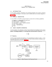
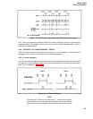
4-48. 5328A PRINCIPLES OF OPERATION
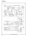
4-49. The 5328A is organized into four main operating sections (refer to Figure 4-8):
• The main counter section
Ž The input section
• The power supply section
• The Hewlett-Packard Interface Bus (HP-IB) section
4-50. Each section operates relatively independently and communicates to the other through an
internal bus system. The two-way bus consists of 90 lines.
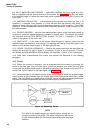
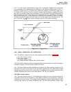
4-51. The power supply provides regulated dc voltage for the other operating sections of the
instrument. The main on-off switch of the instrument operates only the central power supply
regulator; the main ac power line is never broken. Unregulated dc is constantly fed to the oven
oscillator eliminating the need for time base warmup. The fan is dc powered.
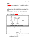
4-52. Main Counter Section
4-53. The main counter section on A1 Motherboard contains all of the functional subunits of
a standard counter with the exception of input signal conditioning and special logic, which are
contained in the input section. The decade counting assembly contains eight decades of BCD
counting logic, latches, and output multiplexing logic. The time base assembly contains eight
4-7