


Intel
®
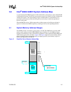
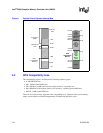
82854 GMCH System Address Map
D15343-003 117
5.4.2.5 PCI Memory Address Range (Top of Main System Memory to 4 GB)
The address range from the top of main DDR SDRAM to 4-GB (top of physical system memory
space supported by the GMCH) is normally mapped via the Hub interface to PCI.
As an internal graphics configuration, there are two exceptions to this rule.
1. The first exception is addresses decoded to the graphics memory range. One per function in
device #2.
2. The second exception is addresses decoded to the system memory mapped range of the
Internal Graphics device. One per function in device #2. Both exception cases are forwarded to
the Internal Graphics device.
There are two sub-ranges within the PCI Memory address range defined as APIC configuration
space and High BIOS Address range. As an Internal Graphics device, the Graphics Memory range
and the Memory mapped range of the Internal Graphics device MUST NOT overlap with these two
ranges. These ranges are described in detail in the following paragraphs.
5.4.2.6 APIC Configuration Space (FEC0_0000h -FECF_FFFFh, FEE0_0000h- FEEF_FFFFh)
This range is reserved for APIC configuration space that includes the default I/O APIC
configuration space. The default Local APIC configuration space is FEE0_0000h to FEEF_0FFFh.
CPU accesses to the Local APIC configuration space do not result in external bus activity since the
Local APIC configuration space is internal to the CPU. However, an MTRR must be programmed
to make the Local APIC range uncacheable (UC). The Local APIC base address in each CPU
should be relocated to the FEC0_0000h (4 GB-20 MB) to FECF_FFFFh range so that one MTRR
can be programmed to 64-kB for the Local and I/O APICs. The I/O APIC(s) usually resides in the
ICH4-M portion of the chip-set or as a stand-alone component(s).
I/O APIC units will be located beginning at the default address FEC0_0000h. The first I/O APIC
will be located at FEC0_0000h. Each I/O APIC unit is located at FEC0_x000h where x is I/O APIC
unit number 0 through F(hex). This address range will be normally mapped to Hub interface.
The address range between the APIC configuration space and the High BIOS (FED0_0000h to
FFDF_FFFFh) is always mapped to the Hub interface.
5.4.2.7 High BIOS Area (FFE0_0000h -FFFF_FFFFh)
The top 2-MB of the Extended Memory region is reserved for System BIOS (High BIOS),
extended BIOS for PCI devices, and the A20 alias of the system BIOS. CPU begins execution
from the High BIOS after reset. This region is mapped to Hub interface so that the upper subset of
this region aliases to 16 MB to 256-kB range. The actual address space required for the BIOS is
less than 2-MB but the minimum CPU MTRR range for this region is 2-MB so that full 2-MB must
be considered.