


Signal Description
D15343-003 35
3.5 Internal Graphics Display Signals
The IGD has support for DVOB/C interfaces, and an Analog CRT port.Digital Video Output B
(DVOB) Port.
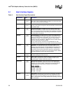
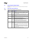
3.5.1 Digital Video Output B (DVOB) Port
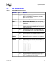
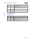
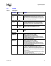
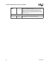
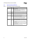
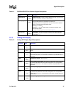
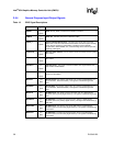
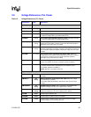
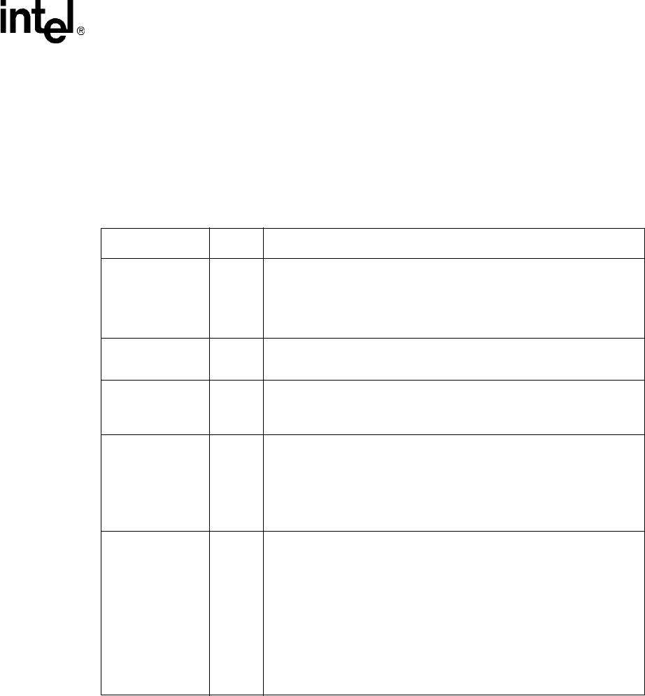
Table 9. Digital Video Output B (DVOB) Port Signal Descriptions
Name Type Description
DVOBD[11:0] O
DVO
DVOB Data: This data bus is used to drive 12-bit RGB data on each edge
of the differential clock signals, DVOBCLK and DVOBCLK#. This provides
24-bits of data per clock period. In dual channel mode, this provides the
lower 12-bits of pixel data.
DVOBD[11:0] should be left as NC (“Not Connected”) if not used.
DVOBHSYNC O
DVO
Horizontal Sync: HSYNC signal for the DVOB interface.
DVOBHSYNC should be left as left as NC (“Not Connected”) if not used.
DVOBVSYNC O
DVO
Vertical Sync: VSYNC signal for the DVOB interface.
DVOBVSYNC should be left as left as NC (“Not Connected”) if the signal
is NOT used when using internal graphics device.
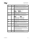
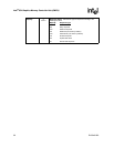
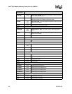
DVOBBLANK# O
DVO
Flicker Blank or Border Period Indication: DVOBBLANK# is a
programmable output pin driven by the GMCH.
When programmed as a blank period indication, this pin indicates active
pixels excluding the border. When programmed as a border period
indication, this pin indicates active pixel including the border pixels.
DVOBBLANK# should be left as left as NC (“Not Connected”) if not used.
DVOBFLDSTL I
DVO
TV Field and Flat Panel Stall Signal. This input can be programmed to
be either a TV Field input from the TV encoder or Stall input from the flat
panel.
DVOB TV Field Signal: When used as a Field input, it synchronizes the
overlay field with the TV encoder field when the overlay is displaying an
interleaved source.
DVOB Flat Panel Stall Signal: When used as the Stall input, it indicates
that the pixel pipeline should stall one horizontal line. The signal changes
during horizontal blanking. The panel fitting logic, when expanding the
image vertically, uses this.
DVOBFLDSTL needs to be pulled down if not used.