


Intel
®
82854 GMCH Strap Pins
D15343-003 151
8.0 Intel
®
82854 GMCH Strap Pins
8.1 Strapping Configuration
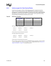
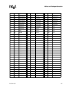
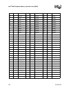
Table 33. Strapping Signals and Configuration
Note: All strap signals are sampled with respect to the leading edge of the Intel
®
82854 GMCH PWROK
In signal.
Pin Name Strap Description Configuration I/F Type Buffer Type
ADDID[0] Native Graphic Mode
select
ADDID[0] = 0, Reserved
ADDID[0] = 1, the Intel
®
82854
GMCH is strapped to operate
under Native Graphic Mode
DVO IN
HSYNC XOR Chain Test Low = Normal Ops (Default)
High = XOR Test On
GPIO OUT
VSYNC ALL Z Test Low = Normal Ops (Default)
High = AllZ Test On
GPIO OUT
LCLKCTLB VTT Voltage Select Low = Default
High = Reserved
GPIO OUT
DVODETECT *DVO Select (If
DVODETECT=0 during
Reset, ADDID[7:0] is
latched to the ADDID
Register)
Low = DVO (Default)
High = Reserved
DVO BI
GST[2] * Clock Config: Bit_2 Please refer to Device #0
Function #3 (HPLLCC Register)
for proper GST[2:0] settings
Please refer to Table 34 for
detail configurations on Intel
854 Straps for Frequency/CPU
DVO Out:
0) Before CPURST#, there is an
internal pull-down
1) Just out of CPURST#: These
pins are Hi-Z
2) C3: these pins are Hi-Z
3) S1-M: these pins are Hi-Z
4) Internal GFX D1/D3: these pins
are Hi-Z
5) S3: these pins are Power down
6) S4/S5: these pins are Power
down
GST[1] * Clock Config: Bit_1
GST[0] * Clock Config: Bit_0
* Please refer to Device #0 Function #2 (ADD_ID – ADD Identification Register) for proper Native Graphic
Mode settings.
External pull-ups/downs will be required on the board to enable the non-default state of the straps.