


Register Description
D15343-003 81
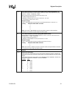
27:26 Back To Back Read-Write commands spacing (DDR, same or different Rows/Bank): This
field determines the RD-WR command spacing, in terms of common clocks based on the following
formula: CL + 0.5xBL + TA (RD-WR) – DQSS
DQSS: is time from Write command to data and is always 1 CK
BL: is Burst Length which is set to 4
TA (RD-WR): is required DQ turn-around, can be set to 1, 2 or 3 CK
CL: is CAS latency, can be set to 2 or 2.5
Examples of usage:
For BL=4, with single DQ turn-around and CL=2, this field must be set to 4 CK (2+2+1-1)
Encoding CK between RD and WR commands
00: 7
01: 6
10: 5
11: 4
NOTE: Since reads in DDR SDRAM cannot be terminated by Writes, the Space between
commands is not a function of Cycle Length but of Burst Length.
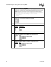
25 Back To Back Read-Read commands spacing (DDR, different Rows):
This field determines the RD-RD Command Spacing, in terms of common clocks based on the
following formula: 0.5xBL + TA(RD-RD)
BL: is Burst Length and can be set to 4.
TA (RD-RD): is required DQ turn-around, can be set to 1 or 2 CK
Examples of usage:
For BL=4, with single DQ turn-around, this field must be set to 3 CK (2+1)
Encoding CK between RD and RD commands
0: 4
1: 3
NOTE: Since a Read to a different row does not terminate a Read, the Space between commands
is not a function of Cycle Length but of Burst Length.
24:15 Reserved
14:12 Refresh Cycle Time (tRFC):
Refresh Cycle Time is measured for a given row from REF command (to perform a refresh) until
following ACT to same row (to perform a Read or Write). It is tracked separately from tRC for DDR
SDRAM.
Current DDR SDRAM spec requires tRFC of 75 ns (DDR266) and 80 ns (DDR200). Therefore, this
field will be set to 8 clocks for DDR200, 10 clocks for DDR266.
Encoding
tRFC
000: 14 clocks
001: 13 clocks
010: 12 clocks
011: 11 clocks
100: 10 clocks
101: 9 clocks
110: 8 clocks
111: 7 clocks