


40930701TH DRAFT Vesion 134 /
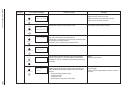
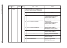
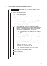
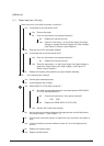
1 The printer does not work normally after being turned on.
• Is message shown in the LCD display (for less than 1 second)?
• No Is the AC cable connected properly?
• No Connect the cable properly.
▼
• No Is the message (16 columns ■ display only on the top row ) shown in the LCD
display?
• Yes Replace the Main board.
▼
• No Are the following voltages applied to the corresponding pins of the POWER
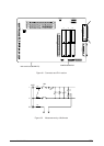
connector on the Main board? (For the measuring points, see Figure 6-1.)
Pin 23: –8V, Pin 24: +8V, Pins 19, 20: +30V
Pins 9-12, 17, 18: 0V, Pins 13, 14: +5V
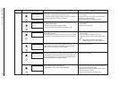
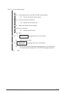
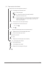
• No Remove the AC cable. Set the POW switch to the ON position.
Measure the resistance between L and N pins of the AC inlet using a
multimeter. Is there continuity between L and N pins (normal resis-
tance: 554 kΩ)? (For measuring points, see Figure 6-2.)
• No Replace the fuse F2 or the Power Supply Unit (AC120V or
230V)
▼
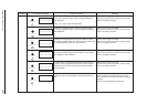
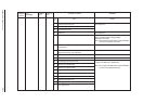
• Yes Are POWER connector of the Main board and Connection cord-Wire
(26 pin) connected properly?
Are connection cord-wire and CN3 connector of the Power Supply
Unit (AC120V or 230V) connected properly?
• No Connect the connectors properly.
▼
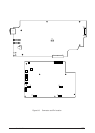
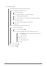
• Yes Are the following voltages applied to CN3 connector of the Power
Supply Unit (AC120V or 230V)? (For measuring points, see Figure 6-
3.)
Pins 19, 20: +30V, Pins 9-12, 17, 18: 0V
Pin 23: –8V, Pins 13, 14: +5V, Pin 24: +8V
• No Replace the Power Supply Unit (AC120V or 230V).
▼
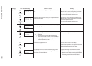
• Yes Replace the Connection cord-wire (26 pin).
▼
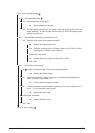
• Is the printer recovered?
• No Replace the Main board
▼
• YES END
1-1
1-2