


40930701TH DRAFT Vesion 39 /
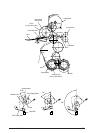
2.3.4 Revision of LED Head Illumination
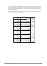
An LED correcting head, which is capable of correcting the illumination of the LED for each dot,
is being used in this printer. LED illumination correction function of 16 steps is carried out by using
an EEPROM which is installed in the LSI that maintains the LED illumination correction values,
and an LED correction drivers together as a pair.
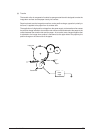
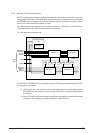
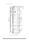
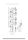
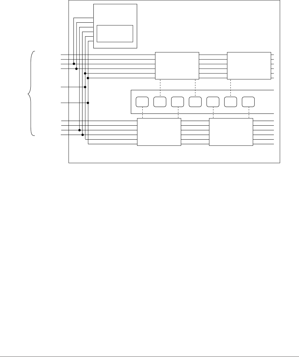
The LED correcting head consists of the correction control LSI , LED drivers , and an LED array.
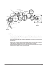
The block diagram of the LED correcting head is shown below.
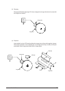
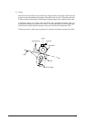
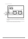
(1) Both sides wire-bonding head
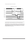
In OKIPAGE 20/ OKIPAGE 20n, the correction control of LED head is excuted direction by CPU.
The procedure is as follows
(i) LED head is set to the correction control read mode and all correction data stored in
EEPROM within the correction control LSI are read by CPU, and stored temporarily in
the memory.
(ii) Next, LED head is set to the correction control direct mode and the correction data stored
temporarily in the memory is transferred directly to the LED driver.
STRB4-N
STRB3-N
DATA 3
DATA 2
LOAD
CLOCK
STRB2-N
STRB1-N
DATA 1
DATA 0
Correction Control
LSI
EEPROM
LED LED LED LED LED LED LED
LED Driver LED Driver
LED Driver LED Driver
LED Array
From
CPU