


40930701TH DRAFT Vesion 3 /
CONTENTS
1. CONFIGURATION ....................................................................................... 7
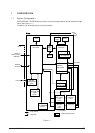
1.1 System Configuration................................................................................................. 7
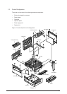
1.2 Printer Configuration .................................................................................................. 8
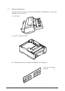
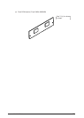
1.3 Optional Configuration ............................................................................................... 9
1.4 Specification............................................................................................................... 11
1.5 Safety Standards ....................................................................................................... 13
1.5.1 Certification label .......................................................................................... 13
1.5.2 Warning label................................................................................................ 13
2. OPERATION DESCRIPTION ...................................................................... 14
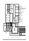
2.1 Main Control Board (BOARD-FFF) ............................................................................ 16
2.2 Power Supply Unit ..................................................................................................... 20
2.3 Electro-photographic Process .................................................................................... 22
2.3.1 Electro-photographic process mechanism ................................................... 22
2.3.2 Electro-photographic process ....................................................................... 24
2.4.3 Process operation descriptions .................................................................... 28
2.3.4 Revision of LED Head Illumination ............................................................... 39
2.4 Paper Jam Detection ................................................................................................. 47
2.5 Cover Open................................................................................................................ 48
2.6 Toner Low Detection .................................................................................................. 49
2.7 Stacker-full Detection ................................................................................................. 51
2.8 Page Size Detection .................................................................................................. 51
3. PARTS REPLACEMENT............................................................................. 52
3.1 Precautions for Parts Replacement ........................................................................... 52
3.2 Parts Layout ............................................................................................................... 54
3.3 How to Change Parts ................................................................................................. 58
3.3.1 Face -up Stacker Assy ................................................................................. 59
3.3.2 Contact Assy ................................................................................................ 60
3.3.3 DC Fan Motor ............................................................................................... 61
3.3.4 OP Panel Assy ............................................................................................. 62
3.3.5 Board-FFF .................................................................................................... 63
3.3.6 Stacker Assy, Damper Arm, Cover Rear..................................................... 64
3.3.7 Sensor Stacker Full ...................................................................................... 65
3.3.8 Cable cover (guide film)................................................................................ 66
3.3.9 Damper ......................................................................................................... 67
3.3.10 Feeder Unit-Front ......................................................................................... 68
3.3.11 Roller Assy-Regist ........................................................................................ 69
3.3.12 Motor -Main .................................................................................................. 70
3.3.13 Guide Assy-Eject .......................................................................................... 72
3.3.14 Heat Assy ..................................................................................................... 73
3.3.15 Roller feed (C) ............................................................................................. 74
3.3.16 Roller Assy-BK ............................................................................................. 75
3.3.17 Roller Assy-Feed .......................................................................................... 76
3.3.18 LED Head ..................................................................................................... 77
3.3.19 Paper cassette, ROLLER Ass-Feed, ROLLER-Assy-Hoppibg ..................... 78
3.3.20 Frame Assy-Separation................................................................................ 79
3.3.21 Transfer Roller/TR Gear/TR Bearing............................................................ 80
3.3.22 EP lock shaft................................................................................................. 81
3.3.23 LEVER Assy- Out Sensor............................................................................. 82
3.3.24 Toner sensor lever........................................................................................ 83
3.3.25 Paper sensor lever ....................................................................................... 84
3.3.26 Inlet sensor lever .......................................................................................... 85