


40930701TH DRAFT Vesion 4 /
3.3.27 Power supply unit ......................................................................................... 86
3.3.28 Lever-Paper end & Lever-Paper near end ................................................... 87
3.3.29 Guide Assy-Cassette (L) .............................................................................. 89
3.3.30 Guide Assy-Cassette (R) .............................................................................. 90
3.3.31 Removing/Installing Duplex Unit................................................................... 92
3.3.32 Board-LEX .................................................................................................... 94
3.3.33 Connector (IMSA-9714N-14A) ..................................................................... 95
3.3.34 Photo Sensor ................................................................................................ 96
3.3.35 SOLENOID Assy .......................................................................................... 97
3.3.36 Motor ............................................................................................................ 98
4. ADJUSTMENT............................................................................................. 99
4.1 Maintenance Modes And Functions........................................................................... 99
4.1.1 User maintenance mode .............................................................................. 101
4.1.2 System maintenance mode .......................................................................... 105
4.1.3 Engine maintenance mode ........................................................................... 107
4.1.4 EEPROM initialization .................................................................................. 111
4.2 Adjustment When Replacing A Part........................................................................... 112
4.2.1 Resetting the fuser counter .......................................................................... 113
4.2.2 Destination setting ........................................................................................ 114
4.2.3 Setting of LED head drive time..................................................................... 115
115
5. PERIODIC MAINTENANCE ........................................................................ 118
5.1 Periodic Replacing Part ............................................................................................. 118
5.2 Cleaning ..................................................................................................................... 118
5.2.1 Cleaning of LED lens array........................................................................... 118
5.2.2 Cleaning the Plastic Film .............................................................................. 119
6. TROUBLESHOOTING PROCEDURES ...................................................... 120
6.1 Troubleshooting Tips ................................................................................................. 120
6.2 Points to Check before Correcting Image Problems .................................................. 120
6.3 Tips for Correcting Image Problems .......................................................................... 120
6.4 Preparation for Troubleshooting ................................................................................ 121
6.5 Troubleshooting Flow................................................................................................. 121
6.5.1 LCD status message/trouble list ................................................................... 121
6.5.2 LCD message troubleshooting ..................................................................... 133
6.5.3 Image troubleshooting .................................................................................. 154
7. WIRING DIAGRAM..................................................................................... 165
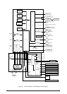
7.1 Interconnect Signal Diagram...................................................................................... 165
7.2 PCB Layout ................................................................................................................ 167
7.3 Resistance Check ...................................................................................................... 170
7.4 Program/Font ROM Location ..................................................................................... 172
8. PARTS LIST ................................................................................................ 174