


40930701TH DRAFT Vesion 96 /
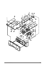
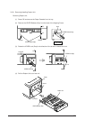
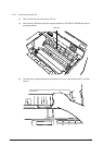
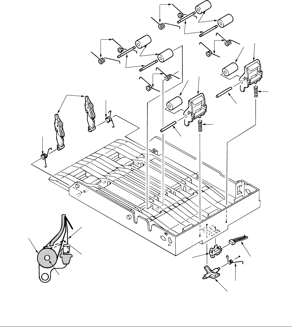
3.3.34 Photo Sensor
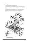
(1) Remove the Frame-Main (DUP) (see section 3.3.2).
(2) Release the lock to remove two SPRING-Lock (frame) 1 and two LEVER-Lock Assy 2.
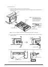
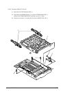
(3) Pull out four SHAFT-Pinch 3 and remove four ROLLER-Pinch 4 and eight SPRING-Pinch
(u) 5.
(4) Release the lock to remove two BRACKET-Pinch 6 , and two SPRING-Pinch(R) 9.
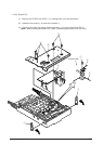
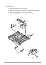
(5) Release the lock to remove LEVER Sensor (D-IN) 0 and SPRING-Sensor A.
(6) Unplug the Connection Code-Wire B and remove Photo Sensor C.
0
A
C
B
1
6
7
8
1
2
5
8
7
9
7
9
6
8
6
5
5
5
3
4
3
4
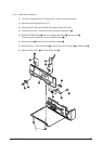
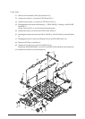
Film-Pinch (R)
Note
: It should not become a state such as of dotted line
from the results of installation.