


40930701TH DRAFT Vesion 5 /
APPENDIX A CENTRONICS PARALLEL INTERFACE .................................... 185
APPENDIX B RS-232C SERIAL INTERFACE ................................................... 189
APPENDIX C SECOND/ THIRD PAPER FEEDER MAINTENANCE ................. 191
1. OUTLINE ................................................................................................................... 191
1.1 Functions ...................................................................................................... 191
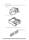
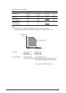
1.2 Appearance and Parts Name ....................................................................... 191
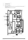
2. Description of operartion ............................................................................................ 192
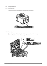
2.1 Driving Mechanism ....................................................................................... 192
2.2 Hopper Mechanism ...................................................................................... 194
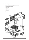
3. PARTS REPLACEMENT ........................................................................................... 195
3.1 Precautions Concerning Parts Replacement................................................ 195
3.2 Parts Layout ................................................................................................. 197
3.3 Parts Replacement Methods ........................................................................ 198
3.3.1 Roller assy hopping, Roller assy feed ............................................. 199
3.3.2 Cover front assy .............................................................................. 200
3.3.3 Board-BBB ...................................................................................... 201
3.3.4 Lever paper end, Lever paper near end.......................................... 202
3.3.5 Motor ............................................................................................... 203
3.3.6 Connector (IMSA-9714N-14B), Connector (IMSA-9714N-14A) ...... 204
3.3.7 Frange pulley, pulley Idle, Mini pitch belt, Plate Earth shaft,
Gear double, Tray switch assy .................. 205
3.3.8 Roller feed ....................................................................................... 206
3.3.9 Bracket sub roller ............................................................................ 207
3.3.10 Frame side (L) assy ........................................................................ 208
3.3.11 Frame side (R) assy ........................................................................ 209
4. TROUBLESHOOTING ............................................................................................... 210
4.1 Precautions Prior to the Troubleshooting ..................................................... 210
4.2 Preparations for the Troubleshooting ........................................................... 210
4.3 Troubleshooting Method ............................................................................... 211
4.3.1 LCD Status Message List................................................................ 211
4.3.2 Troubleshooting Flow ...................................................................... 212
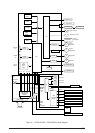
5. CONNECTION DIAGRAM ......................................................................................... 213
5.1 Interconnection Diagram .............................................................................. 213
5.2 PCB Layout .................................................................................................. 214
6. PARTS LIST .............................................................................................................. 215
APPENDIX D MULTI FEEDER MAINTENANCE ................................................ 218
1. OUTLINE ................................................................................................................... 218
1.1 Functions ...................................................................................................... 218
1.2 External View and Component Names......................................................... 218
2. MECHANISM DESCRIPTION ................................................................................... 219
2.1 General Mechanism ..................................................................................... 219
2.2 Hopper Mechanism ...................................................................................... 219
3. PARTS REPLACEMENT ........................................................................................... 220
3.1 Precautions Concerning Parts Replacement................................................ 220
3.2 Parts Layout ................................................................................................. 222