


40930701TH DRAFT Vesion 20 /
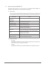
Output voltage Use
+5 V Logic circuit supply voltage
+30 V Motor and fan drive voltage and source voltage for high-voltage supply
+8 V Reset circuit, RS232C Line voltage
–8 V RS232C Line voltage
+3.8V LED HEAD supply voltage
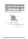
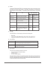
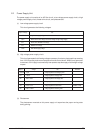
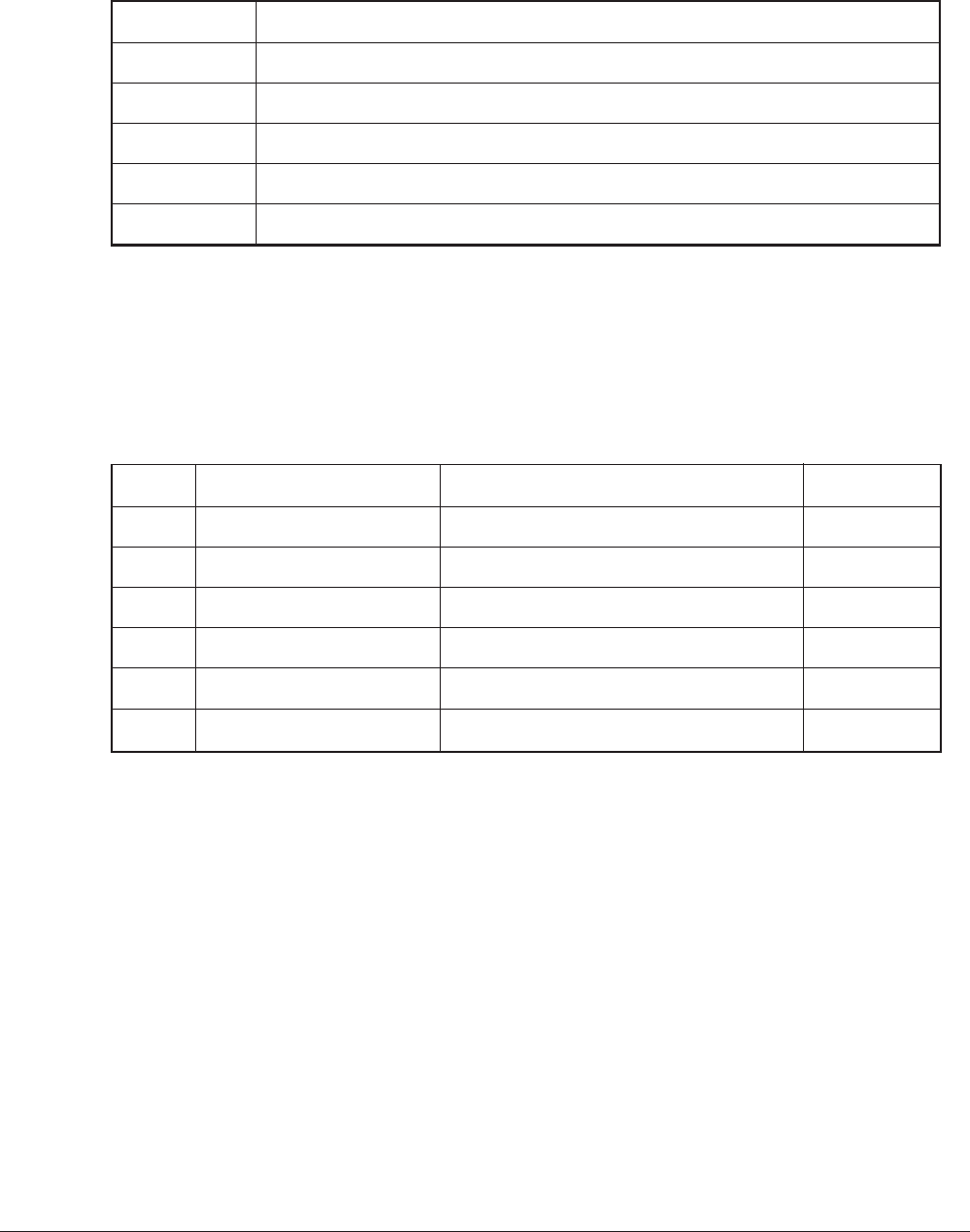
Output Voltage Use Remarks
Sub-CH -15
µ
A Voltage applied to Sub charging roller
CH -1.30 KV Voltage applied to charging roller
DB -220 V/+300 V Voltage applied to developing roller
SB -450 V Voltage applied to toner supply roller
TR +4 KV/-1.3 kV Voltage applied to transfer roller Variable + Only
CB +450 V/-1350V Voltage applied to clearimng roller
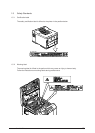
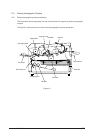
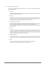
2.2 Power Supply Unit
The power supply unit consists of an AC filter circuit, a low voltage power supply circuit, a high
voltage power supply circuit, heater drive circuit, and photosensors.
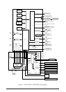
(1) Low voltage power supply circuit
This circuit generates the following voltages.
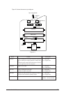
(2) High voltage power supply circuit
This circuit generates the following voltages necessary for electro-photographic processing
from +30 V according to the control sequence from the control board. When cover open state
is detected, +30 V supply is automatically interrupted to stop the supply of all the high-voltage
outputs.
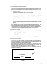
(3) Photosensor
The photosensor mounted on this power supply unit supervises the paper running state
during printing.