


Appendix B – Digital Input Voltage Adjustment
Page 102 09/11/2008 REV 0.99
APPENDIX B – DIGITAL INPUT VOLTAGE ADJUSTMENT
WARNING
TO ELIMINATE THE RISK OF SHOCK ENSURE THAT THE MAINS CABLE AND ALL
CONNECTORS ARE REMOVED FROM THE RECORDER BEFORE PROCEEDING.
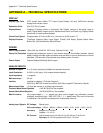
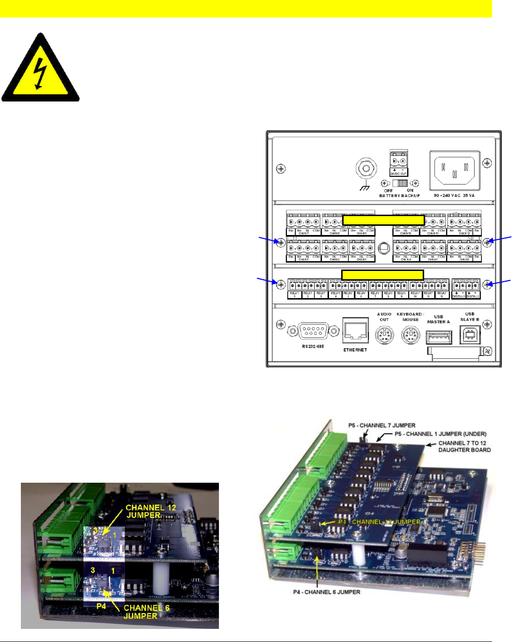
B.1 ANALOG MODULE:
The analog input module accepts frequency inputs
on Channels 1, 6, 7 and 12. By default these inputs
are set up to accept input voltages from 12 to 24
volts dc. The user can change the input voltage
range to 5 to 12 volts dc by moving jumpers
internally on the module. This involves removing the
analog module from the recorder.
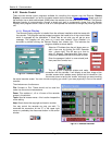
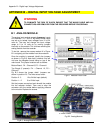
To do this, remove the screws marked A in Figure
B-1 and gently pull the module from the enclosure.
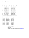
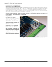
Once the module is removed, identify the jumpers
as shown in Fig B-2. Note that 6 channel units will
not have the daughter board sitting on top of the
main board. The jumper locations are as follows:
Bottom Board: P4 – Channel 6; P5 – Channel 1
Top Board (if present): P4 – Channel 12; P5 –
Channel 7
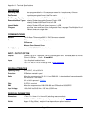
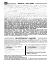
Fig B-3 shows the jumper detail. Jumpers are
shown in position 2-3. The links are as follow:
Position 2 - 3 12 to 24Vdc Input (default)
Position 1 – 2 5 to 12Vdc Input
Set the jumpers as required and reinstall the module
into the recorder chassis. Take care to align the
connector with the socket before applying pressure
to the module. Replace the screws.
A
B
A
B
DIGITAL IO MODULE
ANALOG MODULE
Fig B-1 Recorder Rear Panel
Fig B-3 Analog Module Jumpers
Fig B-2 Analog Module