


Section 3 – Installation
Page 18 09/11/2008 REV 0.99
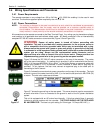
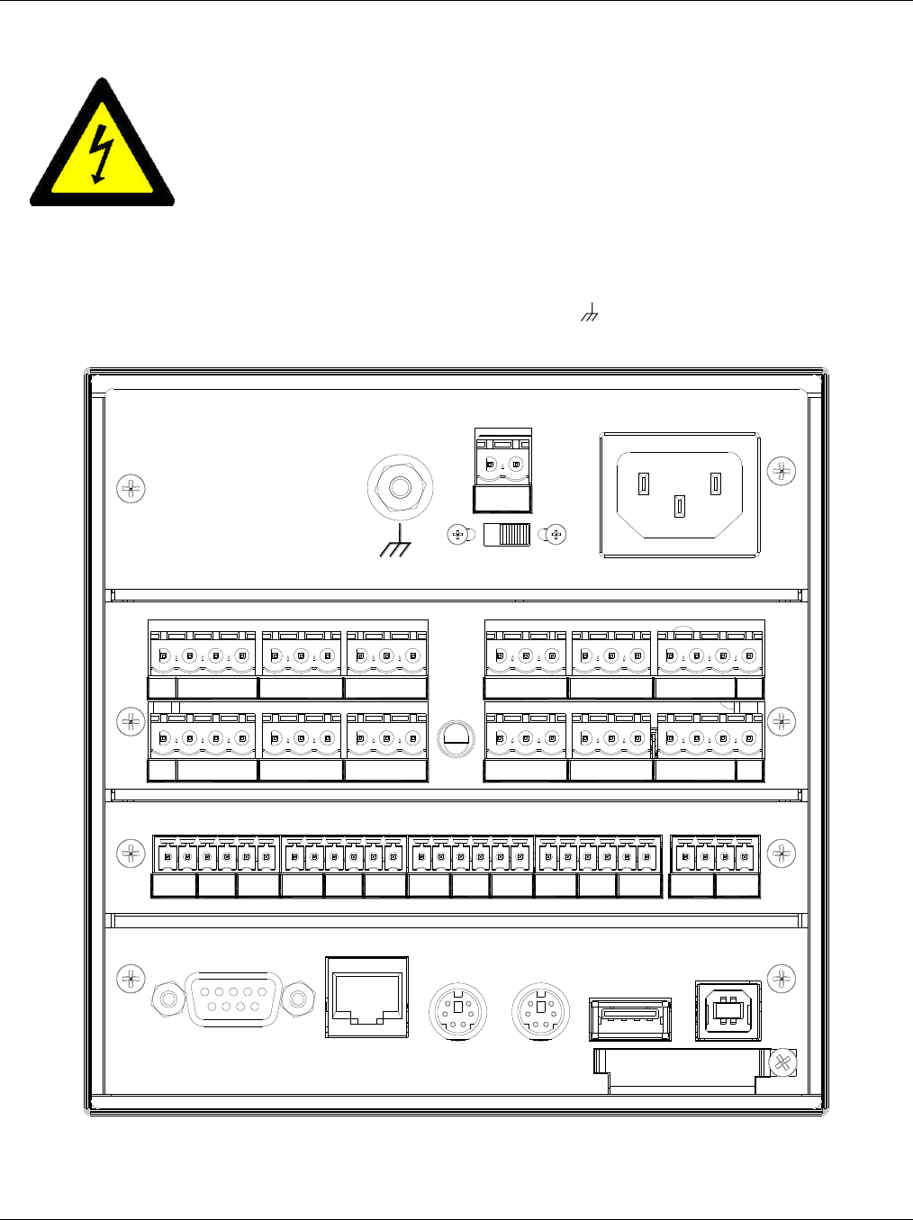
3.4.3 Signal Input Wiring
Signal input connections. Hazardous potentials may exist on signal input terminals
which are floating with respect to case ground. These hazardous potentials may be
on the rear terminal panel of your instrument. Any voltage potential at the signal
source will exist on the instrument’s respective signal input terminal (i.e. power
generator stator winding). The analog inputs can sustain up to 2000 Volts with
respect to the chassis ground.
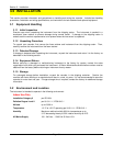
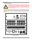
The recorder accepts up to twelve direct inputs. Input connection is via plug in screw terminal connectors on
the rear panel. Inputs can be mixed in any combination of thermocouple, RTD, milliamps, millivolts, volts or
contact inputs. In addition, channels 1 and 6 (and optionally 7 and 12) can accept frequency inputs via an
additional terminal. There is a common ground lug marked with a for connection of signal cable shields
or screens.
COMIN-IN+
CHAN 9
COMIN-IN+
CHAN 8
COMIN-IN+FIN
CHAN 7
CHAN 3CHAN 2CHAN 1
IN+ IN- COMIN+ IN- COMFIN IN+ IN- COM
CHAN 12
IN+ IN- COM FINCOMIN-IN+
CHAN 11CHAN 10
IN+ IN- COM
FINCOMIN-IN+
CHAN 6CHAN 5
IN+ IN- COMCOMIN-IN+
CHAN 4
24VDC OUT
+
-
ON
OFF
BATTERY BACKUP
RELAY
1
RELAY
2
RELAY
3
RELAY
4
RELAY
5
RELAY
6
RELAY
7
RELAY
8
RELAY
9
RELAY
10
RELAY
11
RELAY
12
DIGITAL 1 DIGITAL 2
+ +
-
-
RS232/485
ETHERNET
AUDIO
OUT
KEYBOARD /
MOUSE
90 - 240 VAC 35 VA
USB
MASTER A
USB
SLAVE B
Figure 3.8 – Rear Panel