Section 2 - Overview
Page 10 09/11/2008 REV 0.99
2.7 QUICK START GUIDE
The recorder ships in a fully functional mode, but may not be set up the way you would want to use it and needs
to be configured before it is used.
There are several areas that need to be configured to customize the unit to the user‟s needs. This unique
combination of settings is referred to as the system configuration and is saved in a file called the configuration
file which is physically named config.xml. This file is reasonably human readable and is in XML (Extensible
Markup Language) format. This file resides in the recorder‟s internal memory and is portable. On start-up the
recorder loads this file and configures itself accordingly. There can be numerous configuration files in the
recorder, however only one can be called config.xml. See the Configuration Manager on page 28. If no
configuration file is present at startup, the unit will create one which will have minimal functionality.
The most basic setup needs to define the inputs, create a display and set up a recording. You may need to set
the time and calibrate the touch screen. The setup can then be extended to include alarms, contact outputs
(requires an optional digital I/O module), digital inputs, various display options, and conditional events (like
recording on alarm or sending emails).
The first thing to do is to browse this manual to get some idea of the features of the unit. The following will steer
you to various sections based on a quick set up. Help is available at each screen and you should see the section
on keyboarding before you start anything.
Naming the Recorder: You should give the recorder a unique name to identify it such as “Soap Plant Boiler”.
This is known as the Unit Tag and is entered in the System Setup window.
Analog Setup: You will then need to set up the analog inputs to meet the requirements of the signals you will be
measuring. The recorder has universal inputs capable of measuring a variety of signals from millivolts to Volts,
Current, Resistance, Thermocouples, RTDs and on some channels, Frequency. All channels can also be
assigned as virtual channels, that is they do not have a direct live inputs, but can be Calculated channels, Timers,
Totalizers or Conditional. The analog inputs are set up in the Master Channel Setup menu. Each channel can be
uniquely programmed and has a Channel Tag to identify the channel, eg. “Pump 6”. These settings will apply to
any display objects or widgets that use this channel.
Display Creation: Once the inputs are set up you need some way of displaying the data. This is done on the live
display. To appreciate what this entails check out the section on Display Elements and Widgets. Then use the
Display Builder to create the actual display. This builder allows you to place the widgets on the screen and
customize each and give the display a name. In order to have the display come up on the screen you need to
move it to the Rotate List.
Recording Data: To record data you need to use the Record Setup dialog to select which channels to record,
what to record, at what rate and where to save it. Data can be saved to internal memory, compact flash card or
USB flash drive.
At this point you are ready to connect your signals, watch the data live and record it.
To record the data you must have set up the recorder as mentioned above.
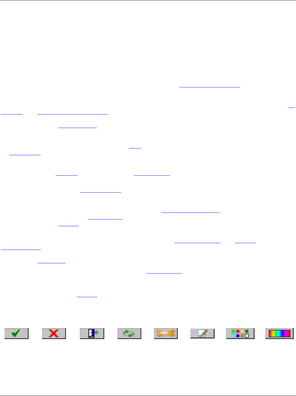
Icon Buttons: There are several buttons with icons used on the recorder. Specific ones are described in the
respective sections. Generic ones are shown below.
