


Section 6 - Communication
Page 87 09/11/2008 REV 0.99
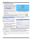
6.3.2 Modbus Server
The recorder supports Modbus
TM
RTU (Remote Terminal Unit) over Ethernet and optional RS485 interfaces.
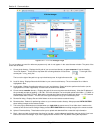
An RS485 interface will support up to 64 Data Recorders linked to a single computer. Each of the Recorders
will be identified by a unique unit address (programmed under System Settings - Modbus). This address is set
at 1 to 256 and must be different from any other recorder on the loop. Similarly if using the RS485 serial port
the baud rate must be set to match the system – 9600 to 115,200 baud.
Modbus over Ethernet is supported through Port 502.
Note that Modbus ASCII is not supported and this recorder supports a minimal subset of registers and is read
only. The functions included in the subset are
Function 3 - Read Holding Registers
Function 4 - Read Input Registers
All Modbus registers are 2 bytes = 1 word.
The physical connection details are shown in Section 2 – Isolated Serial Option.
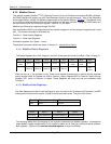
6.3.2.1 Modbus Status Registers
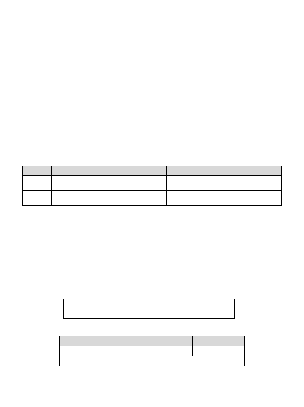
The Status Registers Are 16 bit Integers in the form of two bytes as follows (Low Byte = Bits 0 through 7).
When the bit is a “1” the condition is true. There is one register for each point or channel and the registers
start at number 3056. So Register no. 3056 is Channel 1 status, Register 3057 is Channel 2 status through
Register 3071 which is Channel 18 status. These Registers are read only and are accessed using
Function 4.
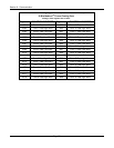
6.3.2.2 Modbus Data Registers
The Data Registers hold the current floating point value for each of the 18 data points (Channels) as IEEE
floating point numbers which require 4 bytes (2 words) as shown below. They are in the format
Sign Bit
Exponent (+127 biased)
Mantissa (Extra implied 1 bit)
1 bit
8 bits
23 bits
The following tables show the mapping of the recorder parameters into Modbus registers. Knowledge of
these Modbus register assignments is only needed to make use of third party communications software.
Both registers – high and low, must be accessed together to ensure valid data.
Bit 15 - 8
Bit 7
Bit 6
Bit 5
Bit 4
Bit 3
Bit 2
Bit 1
Bit 0
Not
Used
0 or 1
0 or 1
0 or 1
0 or 1
0 or 1
Not
Used
Not
Used
0 or 1
Alarm 5
Alarm 4
Alarm 3
Alarm 2
Alarm 1
Any
Alarm
Byte 0
Byte 1
Byte 2
Byte 3
SEEEEEEE
EMMMMMMM
MMMMMMMM
MMMMMMMM
High Word
Low Word