Section 3 – Installation
Page 22 09/11/2008 REV 0.99
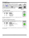
3.6 USB Connection
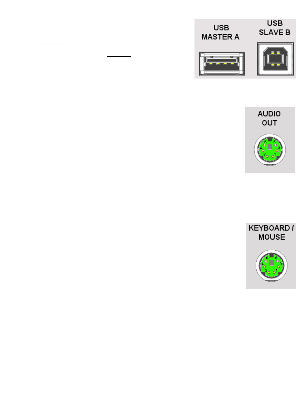
There are two USB (Universal Serial Bus) Connectors on the rear panel.
One is a Type A Master connector; the other is a Type B Slave
connector. Only one can be active at any time – the active connector is
selected by a slide switch on the under side of the recorder close to the
back panel. The switch is set below the surface. Slide the switch toward
the connector you want active – A or B BEFORE powering up the unit.
Use standard shielded USB connector cables to connect to your USB
device (Host PC to USB B – Slave Device to USB A Host port).
Note: Maximum cable length should not exceed 5m (15 feet).
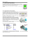
3.7 Audio Connection
The audio output connector is a 6 pin mini din socket that permits connection to the
recorders audio lines. Connections are as follows:
Pin Direction Description
1 Out Audio Common
2 In Microphone Input
3 Out Line Output – Left
5 Out Line Output – Right
4 In Line Input - Left
6 In Line Input - Right
An adapter is available that converts the Mini Din to 3 Standard Phone Jacks for
Microphone In, Line In and Line Out.
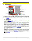
3.8 Mouse and Keyboard Connection
The keyboard / mouse connector is a 6 pin mini din socket that permits connection to an
external mouse and/or keypad. A standard PS2 mouse will plug directly into this socket, a
PS2 keyboard needs an adapter. Connections are as follows:
Pin Direction Description
4 Out +V for Keyboard/Mouse
3 Out Supply Common for Keyboard/Mouse
1 In/Out Mouse Data Line
5 In Mouse Clock Line
2 In/Out Keyboard Data Line
6 In Keyboard Clock Line
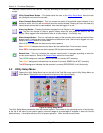
An adapter is available that converts the single Mini Din Socket to two separate sockets, one for the mouse and
one for the keyboard.
Figure 3-13
Figure 3-14
Figure 3-15


