


Section 3 – Installation
Page 21 09/11/2008 REV 0.99
3.4.4 Relay Output, Contact Input
WARNING
To prevent the possibility of electrical shock, use extreme caution when wiring
contact output connections. Hazardous potentials may exist on contact output
terminals which are floating with respect to instrument ground. These hazardous
potentials may be exposed on the rear terminal panel of your instrument. Any
voltage potentials at the contact circuit will exist on the instrument’s respective
contact output terminals (i.e. line-powered circuits).
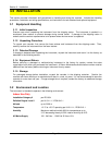
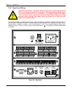
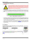
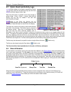
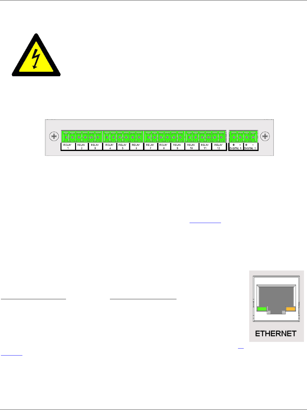
The Recorder may be equipped with an optional Digital Input Output Board which has A combination of up to
12 potential free Form A (Single Pole Normally Open) or Form C (Single Pole Double Throw) relay contacts
and up to 6 opto-isolated digital inputs. The combination depends on the option chosen. An example is shown
below.
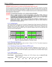
This module has 12 Potential Free Form A Normally Open (NO) connections. Connection is two wire and
there is no polarity. Maximum switching voltage is 200 Vdc and 0.5 Amp at a Maximum of 10 Watts (Voltage
x Current <10W) per contact. The potential free relay contacts are protected internally with 270 volt Metal
Oxide Varistors (MOVs) to prevent contact arcing.
There are two optically isolated digital inputs which accept 12 to 24 volt DC inputs (These can be jumpered
internally on the circuit board for 5 to 12 volt DC operation – see Appendix B). The inputs are polarity aware
and are marked plus (+) and minus (-) accordingly. Check the specification of the specific module in your unit
for full specifications.
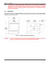
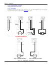
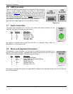
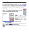
3.5 Ethernet
The 10BaseT Ethernet option allows direct connection to the LAN or WAN and the
standard TCP/IP protocol enables the transfer of data over the Internet. The RJ45
Connection for the Ethernet is as follows:
Receive Differential Pair Transmit Differential Pair
3 RX- 7 TX-
6 RX+ 8 TX+
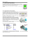
Two LEDs on the rear panel show Ethernet activity. The Amber Link Speed LED indicates
10 or 100 (On) MBpS and the Green RxTx LED indicates communication activity. The IP
address needs to be set before this port will function
Figure 3-11 Digital I/O Module 12 Contacts Out, 2 In
Figure 3-12