


Section 2 - Overview
Page 6 09/11/2008 REV 0.99
AC POWER
INPUT
24 VDC OUTPUT OPTION
SYSTEM GROUND LUG
BATTERY DISCONNECT
ANALOG INPUTS
CHANNELS 7 – 12
(OPTIONAL)
ANALOG INPUTS
CHANNELS 1 – 6
INPUT/OUTPUT
MODULE
(OPTIONAL)
USB TYPE A
(MASTER)
USB TYPE B
(SLAVE)
MEMORY
EXPANSION SLOT
MOUSE/KEYBOARD
CONNECTOR
USB SELECT SWITCH (UNDER)
AUDIO CONNECTOR
SPEED LED
ETHERNET RJ-45
CONNECTOR
ACTIVITY LED
RS-232/RS-485
DB9 CONNECTOR
(OPTIONAL)
AMBIENT
TEMPERATURE
SENSOR
ANALOG INPUT
MODULE
POWER SUPPLY
MODULE
OFF ON
BATTERY BACKUP
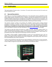
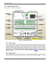
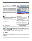
2.4 Recorder Rear Panel
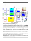
The rear panel of the recorder is shown below:
USB SWITCH
2.4.1 Power Supply
The power supply module is at the top of the recorder rear panel. The rear panel of the universal AC version
is shown in above. On the right is the AC power input socket that takes a standard IEC connector. Screw
terminals are available as an option, as is a DC power supply module. To the left is the optional 24 Volt dc
output option which provides isolated voltage to power external sensors (100mA). Below this is the battery
disconnect switch. The battery is used to enable the system to shut down correctly and survive short power
outages or brown outs. It should be disconnected for storage or shipping purposes. The system-grounding
lug is used to properly ground the recorder on installation. NOTE: See Section 3 for installation and
connection details.
2.4.2 Analog Inputs
The analog input module is available with either 6 or 12 inputs and accepts dc inputs up to +25 volts. These
inputs are isolated from each other and ground and are truly differential. In addition channels 1, 6, 7 and 12
POWER SUPPLY
MODULE
Figure 2-4 Recorder Rear Panel