Section 5 – Recorder Setup
Page 41 09/11/2008 REV 0.99
The resistor (or load) is connected like a 3 wire RTD – See Section 3.0 Installation. Use the Output Low
and High to scale the resistance to the engineering unit of choice.
5.1.3.3 Industrial Square Root Extraction
The recorder accepts the same input types for Industrial Square Root as it does for Linear with the
exception of Dry Contacts. This function is used for inputs which require the Square Root of the input
signal (i.e. flow measurement). The system calculates the square root of the percentage of input scale
and multiplies this value by the high-end scale to produce the value of the point displayed.
In the following example, the input is 4 to 20mA and the scaling is such that 0 = Low End of Scale and
1000 = High End of Scale which represents 1000 gallons per minute.
Let the input Signal = 12mA or 50% of scale which is equal to 0.5
Square Root of 0.5 = 0.707
Actual value displayed is 0.707 x 1000 = 707 GPM (with Decimal fix of 0)
The setup is the same as it is for the Linear input in Section 5.1.3.1.
5.1.3.4 Thermocouples and RTDs
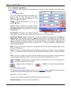
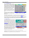
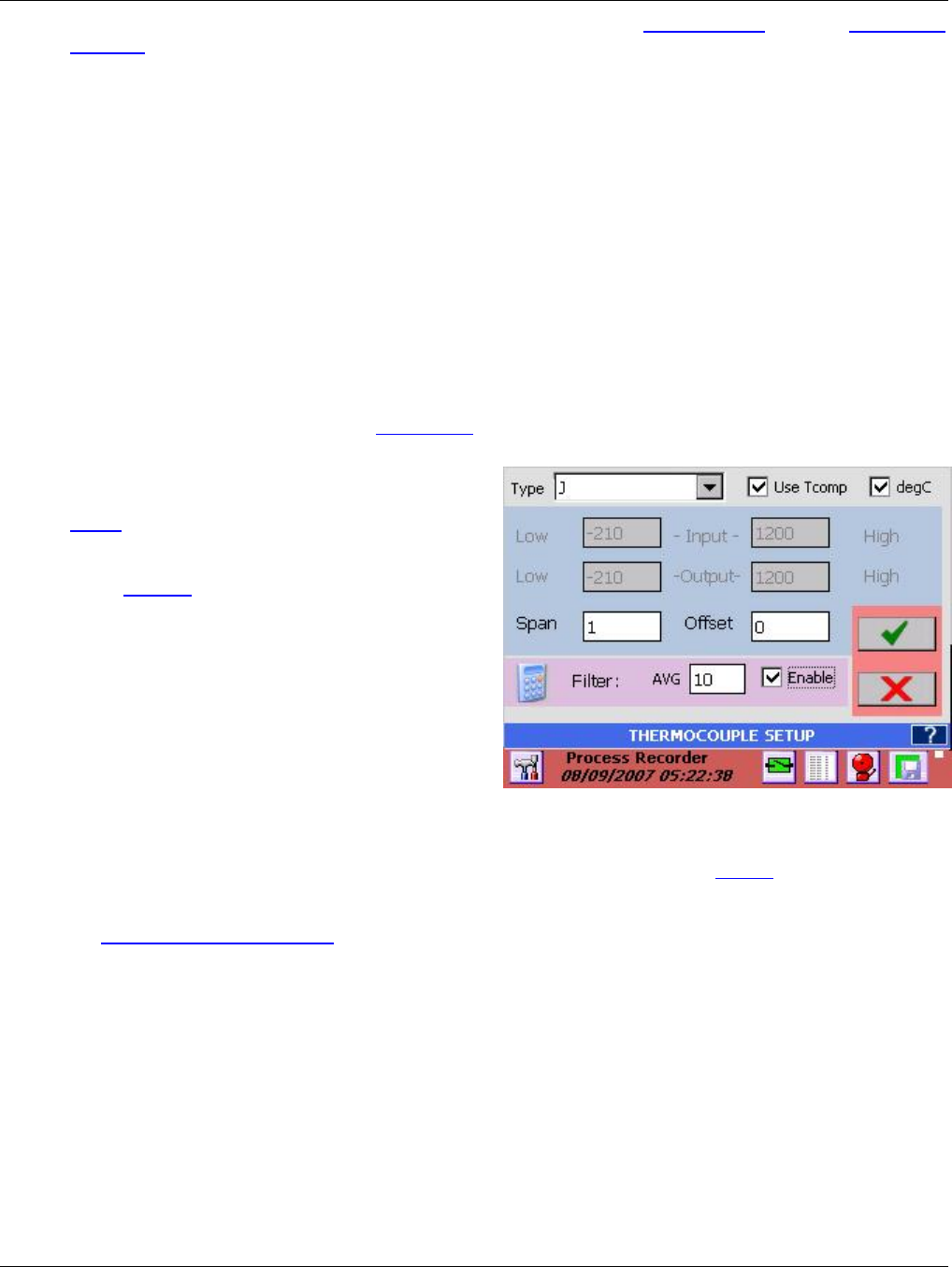
Thermocouple and RTD setup is similar to the
Linear setup except that the Input and Output
scaling cannot be altered. Note that the displayed
scales can be set independently for each widget
– See Widgets for more detail.
Select the Thermocouple (RTD) type from the
drop down menu. The default Engineering Units
is Degrees F. To select Degrees C check the
degC check box.
Thermocouple inputs reference the ambient
temperature compensator on the rear of the unit.
To disable this, uncheck the Use Tcomp
checkbox. The unit will display uncompensated
Thermocouple values.
Apply Span and Offset as needed and select Filter type as detailed in Section 5.1.3.1. above.
Note: For thermocouples, the ambient temperature compensation can be adjusted in 0.5° increments in
the Temperature Compensation menu of the Admin Setup Menu.
Figure 5-4 Thermocouple Setup


