


Section 5 – Recorder Setup
Page 38 09/11/2008 REV 0.99
5.0 RECORDER SETUP
The recorder can be fully customized and needs to be set up by the user. The setup is saved in configuration
files, which can be saved and loaded by the user. Several configurations are shipped with the unit and can be
used as a starting point or the user can start with a clean slate and create a unique configuration.
5.1 Input Channels
The recorder has 18 channels that need to be configured and set up. The setup for the channels requires defining
the inputs. Channels 1 to 12 (channels 7 to 12 are optional) can be live inputs – analog or digital. Channels 13 to
18 or any other channel not assigned to a live input can be a virtual channel. Unused channels should be set as
unassigned. The channels can be:
Analog: Linear – Voltage or Currents, Resistance, Thermocouples, RTD‟s
Square Root Extraction - Voltage or Currents
Digital: Logic input (Dry Contacts).
Frequency Input. Channels 1,6,( optionally 7,12) can accept frequency inputs (Frequency,
Period, Count, Pulse Width, Duty Cycle)
Virtual: All channels not assigned above can be Computational, Conditional, Gated Timers or
Totalizer channels. Although not directly linked to live inputs, these channels can be indirectly
associated with live inputs through the computational and conditional options.
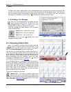
5.1.1 Master Channel Setup
The Master Channel Setup window is a one stop
shop to quickly set up all the channels or get a
general overview of channel setup. If passwords
are enabled the user has to log in as Administrator
in order to access. NOTE: You cannot use this
option if the unit is in the record mode – you need to
stop the recording first (See Section Record Setup).
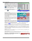
To access the Master Channel Setup window:
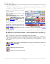
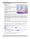
Press the Utility Setup Menu icon on the
bottom left of the Task Bar.
Then press the Master Channel Setup
icon.
NOTE: It takes the recorder a while to build the
setup display as shown right.
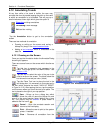
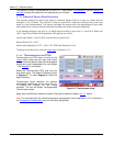
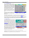
The Master Channel Setup dialog window shows the current setup of all the channels and allows the user to
edit each of them individually. The checkboxes show whether the channel and its alarms are enabled.
You can see the current settings for Input Type, Range and Engineering Units. For example in Figure 5-1,
Channel 2 is set up as a Gated Timer with engineering units of Seconds. The channel is enabled and the
alarms are disabled.
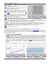
Tap the double arrow button to view the other 12 channels. In order to change the setups it is
necessary to use the edit button. Pressing the edit button takes you to the individual channel
setup menu. When you have completed the channel setups press the done button to return.
Figure 5-1 Master Channel Setup